Replacing the left intake VANOS adjuster
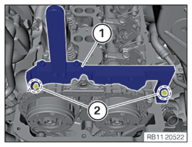
- Position special tool 2 249 117 (1) on the camshafts of cylinder bank 2.
- Secure camshafts with the special tool 2 249 117 (1).
- Hand-tighten special tool 2 249 117 using 2 of the cylinder head cover screws (2) until it is against the cylinder head.
Damage to timing chain or timing chain drive.
Turning the engine without chain tensioner or special tool can result in damage to the timing chain and timing chain drive.
- Always turn the engine with the chain tensioner or the special tool.
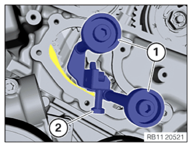
- Release timing chain on the special tool 2 249 162 by turning the hexagon screw (2).
- Leave the special tool 2 249 162 (1) in the cylinder head.
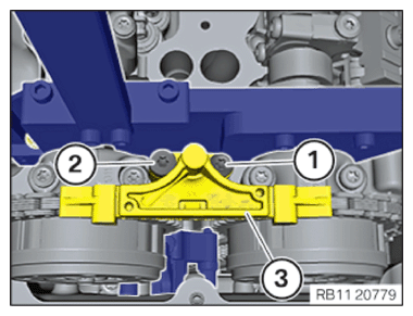
- Loosen screw (1).
- Loosen screw (2).
- Remove the slide rail of cylinder bank 2 (3).
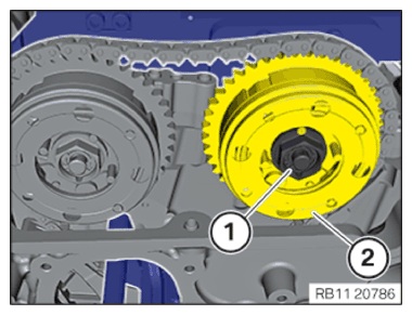
- Loosen the VANOS central valve (1).
The exhaust camshaft adjuster and the intake adjuster may not be detached from the camshafts during the procedure.
- Loosen and remove VANOS central valve (1).
- Pull out and remove VANOS adjuster (2).
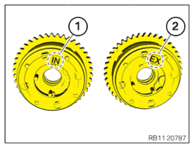
- Always check the installation position of the VANOS adjusters.
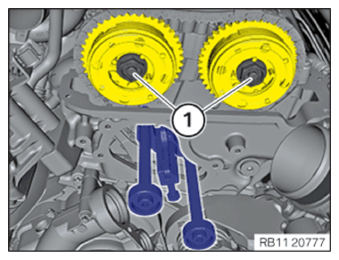
IN is the intake camshaft adjuster (1).
EX is the exhaust camshaft adjuster (2).
- For replacement: Replace VANOS adjuster (2).
Parts: VANOS unit
- Insert and position the VANOS adjusters (2).
The VANOS adjuster (2) must be flush with the camshaft.
- Hand-tighten VANOS central valve (1).
- Hand-tighten VANOS central valve (1).
- Position the slide rail of cylinder bank 2 (3).
- Tighten down screw (2).
| Flat-head screw to the slide rail | ||
| Flat-head screw M6x67 | Tightening torque | 10 Nm |
- Tighten down screw (1).
| Collar screw to the slide rail | ||
| Collar screw M6x48 | Tightening torque | 10 Nm |
Damage to timing chain or timing chain drive.
Turning the engine without chain tensioner or special tool can result in damage to the timing chain and timing chain drive.
- Always turn the engine with the chain tensioner or the special tool.
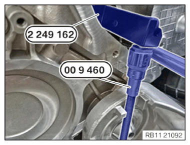
- Position the special tool 2 249 162 on the cylinder head and apply the screws (1) hand-tight.
- Exchange the screw (2) on the special tool 2 249 162 with an (M8x15) hexagon screw.
- Pretension special tool 2 249 162 using special tool 0 496 778 (00 9 460) at 0.6 Nm.
The flexible shaft on the special tool 0 496 778 (00 9 460) must not touch any other components, as the torque value will be falsified.
| Preload timing chain | ||
| tightening torque | 0.6 Nm | |
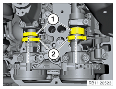
- Place lines near the hexagon head on the VANOS central valves (1) and the VANOS adjusters (2).
The angle must be 60°.
- Turn VANOS central valves (1) counterclockwise near the hexagon head to loosen until the top mark on the VANOS central valve lines up with the bottom mark.
The rotational angle must be 60°.
- Rotate the engine counterclockwise 90° on the central bolt.
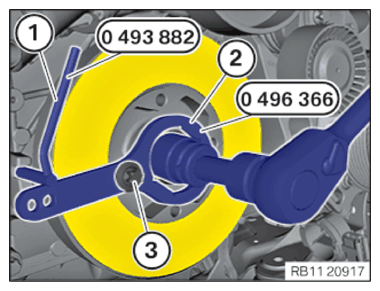
- Make sure the special tools (1) 0 493 882 (11 9 190) and 0 496 366 (11 8 570) (2) do not collide with other components.
- Remove the special tools 0 496 366 (11 8 570)
(2).
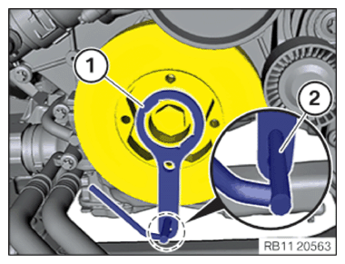
- Position special tool (1) 0 493 882 (11 9 190) in the recess in the engine block.
- Rotate engine on the central bolt clockwise until the special tool 0 493 882 (11 9 190) (1) is against the special tool 0 496 366 (11 8 570) (2).
- Attach the special tool 0 496 366 (11 8 570) (3) to the vibration absorber with a screw from the belt pulley (2) and hand-tighten.
- Remove the special tool (1) 0 496 366 (11 8 570) .
- Check the preload on the special tool 2 249 162 with the special tool 0 496 778 (00 9 460) with 0.6 Nm.
The flexible shaft on the special tool 0 496 778 (00 9 460) must not touch any other components, as the torque value will be falsified.
| Preload timing chain | ||
| tightening torque | 0.6 Nm | |
- Tighten VANOS central valves (1).
| VANOS central valve initial torque | ||
| VANOS central valve | Joining torque | 5 Nm |
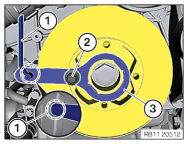
- Rotate engine on the central bolt until the special tool lines up with the engine block bridges.
- The special tool 0 496 366 (11 8 570) (3) must be fastened to the vibration absorber with a screw from the belt pulley (2).
- With the crankshaft in the installation position, use the special tool 0 493 882 (11 9 190) (1) to insert it onto the bridges and fasten.
- Tighten VANOS central valves (1).
| VANOS central valve second tightening | ||
| VANOS central valve | Joining torque | 30 Nm |
| Joining torque | 50 Nm | |
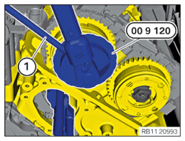
- Position special tool 0 490 504 (00 9 120)
(1) on the VANOS central exhaust valve.
The magnetic base of the special tool 0 490 504 (00 9 120) must be attached to a magnetic component in the engine compartment.
- Make sure the flexible element of the special tool 0 490 504 (00 9 120)
(1) does not collide with other components.
- Set the dial gauge on the special tool 0 490 504 (00 9 120) to zero.
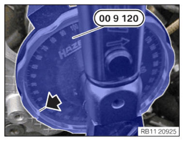
- Tighten VANOS central intake valve until the needle on the special tool 0 490 504 (00 9 120) is at 30°.
| VANOS central valve third tightening | ||
| VANOS central valve | Angle of rotation | 30° |
- Position special tool 0 490 504 (00 9 120)
(1) on the VANOS central intake valve.
The magnetic base of the special tool 0 490 504 (00 9 120) must be attached to a magnetic component in the engine compartment.
- Make sure the flexible element of the special tool 0 490 504 (00 9 120) (1) does not collide with other components.
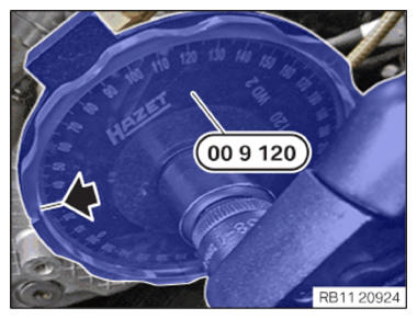
- Set the dial gauge on the special tool 0 490 504 (00 9 120) to "0".
- Tighten VANOS central intake valve until the needle on the special tool 0 490 504 (00 9 120) is at 30°.
| VANOS central valve third tightening | ||
| VANOS central valve | Angle of rotation | 30° |
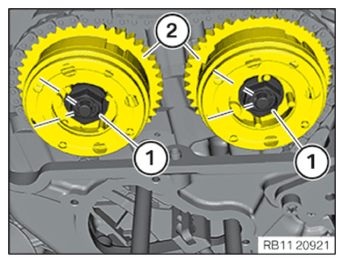
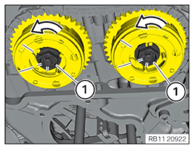
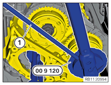
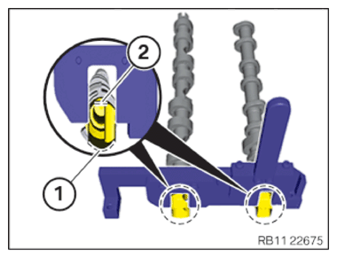
- Check the camshaft position of cylinder bank 2.
The cams (1) should be in the position shown.
The increment wheels (2) should each form a straight line with the exhaust camshaft bearing cap and the intake camshaft bearing cap.
- Ensure that the polished surfaces of the camshafts (2) point upward.
- Ensure that the rounded surfaces (1) are pointing down at the cylinder head.
- Check timing again and assess.
- Loosen screws (2).
- Remove the special tools 2 249 117
(1).
- Remove the special tool 0 493 882 (11 9 190) (1).
- Release the screw of the belt pulley (2).
- Remove the special tool 0 496 366 (11 8 570)
(3).
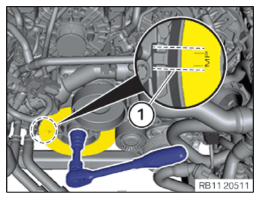
- Crank the engine at the central bolt in clockwise direction two times until the installation position (1) of the vibration absorber is positioned flush with the marks of the engine block.
- Position special tool 0 496 366 (11 8 570) (3) on the vibration absorber.
- Position special tool 0 493 882 (11 9 190)
(1) in special tool 0 496 366 (11 8 570)
.
Do not slide the special tool 0 493 882 (11 9 190) (1) too far in; otherwise, it will collide with other components when the crankshaft is turning.
- Rotate the engine on the central bolt in direction of engine rotation until the special tool lines up with the engine block marks.
- Attach the special tool 0 496 366 (11 8 570)
(3) to the vibration absorber with a screw from the belt pulley (2) and hand-tighten.
- With the crankshaft in the installation position, use the special tool 0 493 882 (11 9 190)
(1) to insert it onto the marks and fasten.
Check
- Position special tool 2 249 117 (1) on the camshafts of cylinder bank 2.
- Check if the camshafts can be fastened with the special tool 2 249 117 (1).
- Check if the special tool 2 249 117 can be brought in contact with the cylinder head using the two screws of the cylinder head cover (2).
Result
» The camshafts can be fastened.
Timings are correct.
Measure
- Loosen screws (2).
Remove the special tools 2 249 117 (1).
Continue the repair in the next step.
Result
» The camshafts cannot be fastened.
Measure
- Adjust the timings of cylinder bank 2.
- Remove the special tool 0 493 882 (11 9 190) (1).
- Release the screw of the belt pulley (2).
- Remove the special tool 0 496 366 (11 8 570)
(3).
- Loosen screws (2).
- Remove the special tool 2 249 117 (1).