Installing the repair cable set (in vehicles until 07/2020)
Deactivating the 48 V electrical system
Prerequisite
Ignition is switched off.
Risk of short circuits! Risk of fire!
- Make sure that there is no battery charger connected to the jump start terminal in the engine compartment.
- For vehicles with additional electrical systems (48 V electrical system, high-voltage vehicle electrical system), this absolutely must be deactivated before the vehicle battery is disconnected.
Risk of short circuits! Risk of fire!
- Make sure that there is no charger connected to the jump start terminal in the engine compartment.
Damage to the 48-V battery
If a 48-V battery that is disconnected from the electrical system is activated, the battery electronics will be damaged.
- Only ever activate the 48 V electrical system when the 48 V battery is fully connected up.
Observe NOTES ON THE 48-V BATTERY .
- Deactivate the 48 V electrical system by opening the hood.
Deactivation is automatic.
Check
Zero voltage (48 V electrical system switched-off) is only displayed in PAD mode.
- Press the START-STOP button quickly 3 times without stepping on the brake pedal to establish the PAD mode.
- Check the de-energized state in the instrument cluster (KOMBI) in the PAD mode.
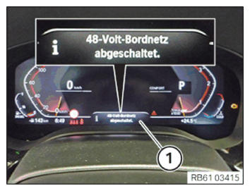
Desired state
- The Check Control message "48 V electrical system." switched off (1) is displayed.
Result
» Absence of voltage cannot be specified with the Check Control message "48 V electrical system switched off." (1). Work start is not permitted.
Measure
- Repeat the "deactivate 48 V electrical system" service function.
- Vehicle management > service function > voltage supply > deactivate 48 V electrical system
Only if the Check Control message "48 V electrical system switched off." (1) is displayed in the instrument cluster (KOMBI), the 12V battery may be disconnected.
Contact the technical support if the absence of voltage is not clearly given.
Result
» The Check Control message reports that 48 V electrical system is switched off.
Measure
- Exit PAD mode by pressing the START-STOP button once without stepping on the brake pedal.
"Disconnect the negative battery cable of the 48-V battery" work can be started.
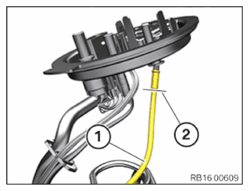
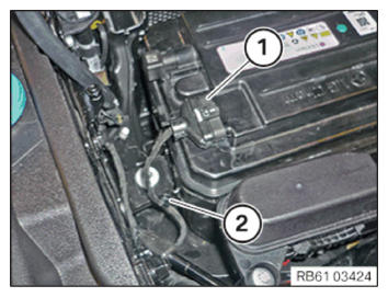
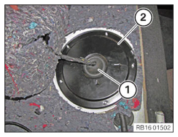
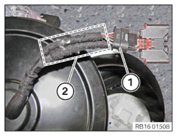
- Unlock and disconnect the CAN bus plug connection (1) of the gear sensor.
- Release the clip (2).
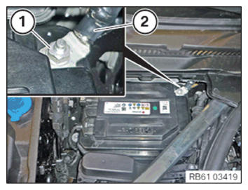
- Loosen nut (1).
- Detach the negative battery cable (2) of the 48-V battery from the negative battery terminal, set to one side and secure.
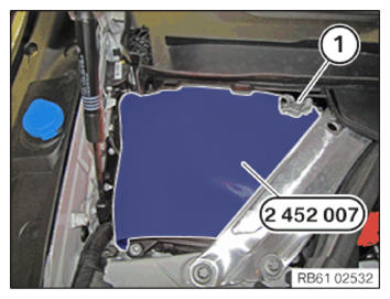
Risk of short circuits! Risk of fire!
- Cover the vehicle battery.
- Cover the vehicle battery with the special tool 2 452 007 as shown.
- Position the battery ground lead (1) as shown.
Disconnecting all battery ground leads
- See ADDITIONAL INFORMATION
.
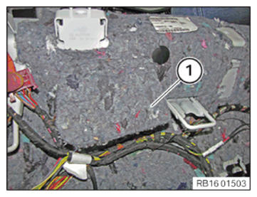
- Guide out seal (1) from cover (2).
- Unfold sound insulation (1).
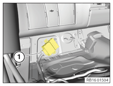
- Unlock plug connection (1) and disconnect.
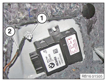
- Release nut (1).
- Remove the grounding cable (2).
Installing the repair wiring harness
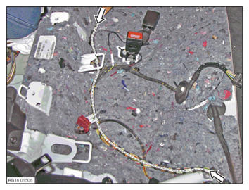
- Carefully remove the insulating tape from wiring harness on the side of vehicle along the marked length in arrow direction.
The wiring harness must not be damaged in the process.
- Place the repair wiring harness on the vehicle side wiring harness.
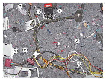
- Unpin the following four pins of the vehicle-side connector (2) and install pins in the connector (1) of the repair wiring harness:
Pin Color 2 red-green 5 red 7 violet-white 9 green-violet - Crimp the following wires from repair wiring harness (3) with the corresponding wires from the vehicle-side wiring harness in the area (4) using the butt connector.
| Color |
|---|
| yellow-green |
| yellow-blue |
| yellow-white |
Connector A248*1B is only required in certain national-market versions.
- If connector A248*1B on the vehicle-side wiring harness is not present (see next step in the illustration):
Do not crimp other wires.
Tie wires together at the ends with insulating tape.
The wires and the connector A248*1B are not required.
- If connector A248*1B is installed (see next step in illustration):
Remove the wrapping from the wiring harness on the side of vehicle to the connector A248*1B.
Retrace the wires on the vehicle-side wiring harness from the connector A248*1B to the point (4) and crimp it with the corresponding wires from the repair kit using the butt connector.
| Pin | Color |
|---|---|
| 1 | gray-violet |
| 2 | brown |
| 3 | black-red |
| 4 | red |
| 5 | gray-white |
Crimp the vehicle-side wire (6) with the wire from the repair cable set using the butt connector.
| Color |
|---|
| black-red |
- Remove the remaining from wiring harness on the side of vehicle.
- Fasten the repair wiring harness on the position (5) using the cable tie.
- Wrap the repair wiring harness from position (7) to position (4) with insulating tape.
- If connector A248*1B (1) is not needed:
Fasten the connector A248*1B (1) to the wiring harness using insulating tape in the area (2).
- Position the (2) grounding cable.
- Tighten nut (1).
| Ground cable to body | ||
| M6 | Tightening torque | 8 Nm |
- Install seal (1) in cover (2).
Disconnecting all battery ground leads
- See ADDITIONAL INFORMATION .
Activating the 48 V electrical system
Prerequisite
Ignition is switched off.
Damage to the 48-V battery
If a 48-V battery that is disconnected from the electrical system is activated, the battery electronics will be damaged.
- Only ever activate the 48 V electrical system when the 48 V battery is fully connected up.
- Raise the battery ground cable (1).
- Remove special tool 2 452 007.
- Release the negative battery cable (2) of the 48-V battery from the attachment.
- Position the negative battery cable (2) of the 48-V battery on the negative battery terminal.
- Tighten the nut (1).
| Negative battery cable to 48-V battery | ||
| Nut M8 | Tightening torque | 19 Nm |
- Connect the connector (1) of the CAN bus and lock it.
- Clip in the clip (2).
- Activate the 48 V electrical system by closing the hood.
The activation takes place automatically.