Removing the rail with injectors
NOTE:
DANGER
High-voltage system.
The high-voltage system operates on the basis of hazardous, electrical voltage and high currents. Mortal hazard through electric shock!
High-voltage system.
The high-voltage system operates on the basis of hazardous, electrical voltage and high currents. Mortal hazard through electric shock!
- All work on the high-voltage system may only be carried out by specially trained and technically experienced personnel.
- For additional information see:
- For additional information see:
WARNING:
Working on 12 V electrical system.
Risk of short circuits! Risk of fire!
Risk of short circuits! Risk of fire!
- Make sure that there is no charger connected to the jump start terminal in the engine compartment.
- Detach battery ground lead from battery.
- For auxiliary batteries: Detach battery minus cables from all auxiliary batteries.
NOTE:
RISK OF DAMAGE
Damage to battery terminal, the safety battery terminal or the intelligent battery sensor (IBS).
Damaged battery terminals can lead to malfunctions or vehicle electrical system faults.
Damage to battery terminal, the safety battery terminal or the intelligent battery sensor (IBS).
Damaged battery terminals can lead to malfunctions or vehicle electrical system faults.
- Detach battery terminal from battery pole by carefully shifting to and fro. Do not pry off using a tool.
Preliminary work
- Refer to DISCONNECTING ALL BATTERY GROUND LEADS .
- Refer to REMOVE THE SEAL FOR THE HOOD REAR .
- Refer to REMOVING THE ACOUSTIC COVER .
- Refer to REMOVING ACOUSTIC COVER AT REAR
- Refer to REMOVE ALL IGNITION COILS .
- Refer to REMOVE THE CYLINDER HEAD COVER ACOUSTIC COVER .
- Refer to REMOVE THE HIGH PRESSURE LINE BETWEEN THE HIGH PRESSURE PUMP AND THE RAIL .
Further information is available.
NOTE:
RISK OF DAMAGE
Damage to injectors.
Excessive force may damage the injector and this means having to replace the injector.
Damage to injectors.
Excessive force may damage the injector and this means having to replace the injector.
- Twist the injectors with a torsional movement of maximum 13 Nm.
NOTE:
RISK OF DAMAGE
Damage to the injector tips and Teflon ring.
Improper handling of the injector tips and Teflon ring can lead to malfunctioning of the injector.
Damage to the injector tips and Teflon ring.
Improper handling of the injector tips and Teflon ring can lead to malfunctioning of the injector.
- Avoid mechanical contact with injector tip.
- When exchanging Teflon ring, hands and work surface must be clean and free of oil. Do not use any lubricating agents.
- Do not use fingernails to slide Teflon ring on.
NOTE:
RISK OF DAMAGE
Contaminant or foreign body.
Contamination can result in malfunctions, loss of function or leaks.
Contaminant or foreign body.
Contamination can result in malfunctions, loss of function or leaks.
- Adhere to the utmost cleanliness.
- Protect components from contamination e.g. by covering.
- Close off line connections with seal plugs.
NOTE:
RISK OF DAMAGE
Electrostatic discharge.
Damage to or destruction of electrical components.
Electrostatic discharge.
Damage to or destruction of electrical components.
- Leave the electrical components in their original packaging until they are being installed. Only use the original packaging for returning the product. Always package removed components straight away.
- Read and comply with user information on using the associated special tool 12 7 060.
- Only tap the housings of electrical components. Do not tap pins or multi-pin connectors directly.
- Wear electrically conductive clothing and antistatic shoes (with ESD symbol).
- For additional information see: 61 35... NOTES ON ESD (ELECTROSTATIC DISCHARGE) PROTECTION
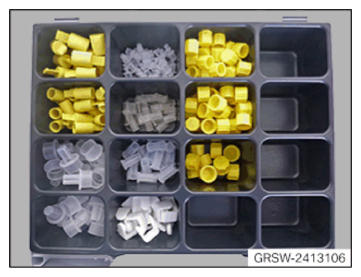
- Prepare special tool 2 413 106
.
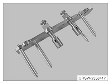
- Prepare special tool 2 358 417
.
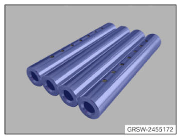
- Prepare special tool 2 455 172
.
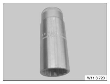
- Prepare special tool 0 496 106 (11 8 720)
.
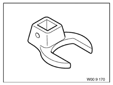
- Prepare special tool 0 490 507 (00 9 170)
.
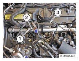
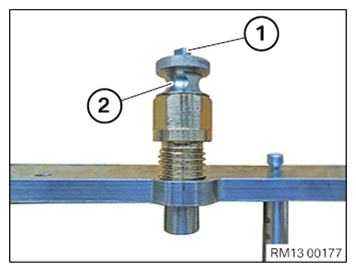
- Loosen nut (1).
- Feed out ground cable (2) and set it aside.
- Feed out cable duct (3) and set it aside.
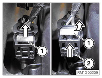
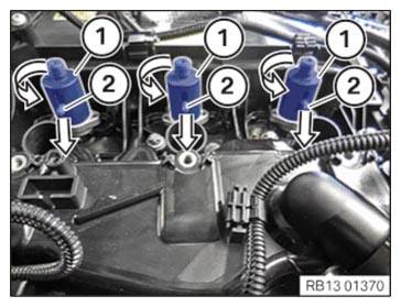
- Unlock lock (1) arrow direction from the top.
- Press lock (1) together and release.
- Detach connector (2) from the injectors.
NOTE:
RISK OF DAMAGE
Damage to wires when disconnecting connectors and plug connections.
Sheared wires can cause a short circuit.
Damage to wires when disconnecting connectors and plug connections.
Sheared wires can cause a short circuit.
- Do not pull on wires when disconnecting connectors and plug connections.
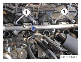
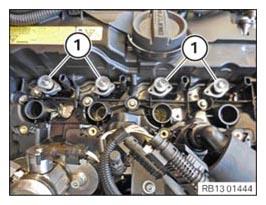
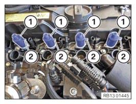
- Unlock and release all connectors (1) of the injectors.
NOTE:
TECHNICAL INFORMATION
When the vehicle is under dusty/sandy operating conditions, the injector shafts must be cleaned before removing the injectors.
For additional information see: 13 53... CLEANING THE CYLINDER HEAD IN AREA OF INJECTORS IF THERE IS SANDY/DUSTY CONTAMINATION
When the vehicle is under dusty/sandy operating conditions, the injector shafts must be cleaned before removing the injectors.
For additional information see: 13 53... CLEANING THE CYLINDER HEAD IN AREA OF INJECTORS IF THERE IS SANDY/DUSTY CONTAMINATION
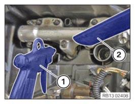
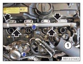
- Before releasing the high pressure lines: Blow out the injector shafts with an air gun (1) using little pressure.
- At the same time suction up the dirt particles with an explosion-proof vacuum cleaner (2).
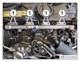
- Unscrew and remove the screws (M5x30) (1).
- Do not reuse the screws (M5x30) (1).
- Replace the screws (M5x30) (1).
Parts: Screws (M5x30)
- Catch and dispose of leakage fuel with suitable materials.
- Unscrew and remove screws (M6x70) (arrows).
Do not reuse the screws (M6x70) (arrows).
- Replace the screws (M6x70) (arrows).
Parts: Screws (M6x70)
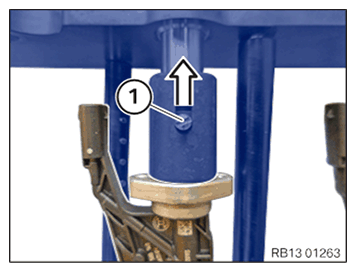
- Unlock plug connection (1) and disconnect.
- Remove rail upwards.
The injectors remain in the cylinder head.
- Remove the gaskets (1).
The seals (1) are only required during the initial installation at the plant and will not be installed again.
NOTE:
RISK OF DAMAGE
Damage to injectors.
Excessive force may damage the injector and this means having to replace the injector.
Damage to injectors.
Excessive force may damage the injector and this means having to replace the injector.
- Twist the injectors with a torsional movement of maximum 13 Nm.
- In the event that the specified value for the tensile force is exceeded: Replace injectors.
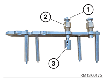
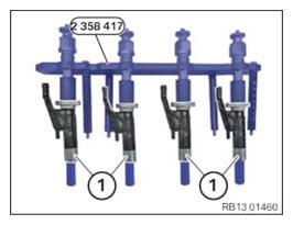
- Use special tool 2 358 417
with special tool (spacer sleeves) 2 455 172
to remove the injectors.
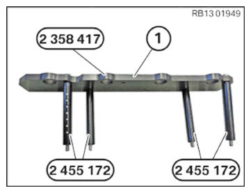
The special tool 2 358 417 and the spacer sleeves 2 455 172 ensure that the tensile force is not exceeded.
The special tool 2 358 417 consists of:
- (1) Threaded sleeves
- (2) Pull-out thread (left-hand thread)
- (3) Mount for the injector
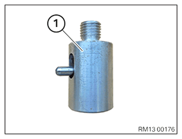
- Unscrew the stand for the injectors (1) from the special tool 2 358 417
.
- Press the lock (1) and remove threaded sleeve (2) from the special tool 2 358 417
.
- Install all stands (1) for the injectors.
The mountings (1) are not yet locked when the levers (2) are up.
- Turn the mounts (1) in the direction of the arrow by 90°
and lock the levers (2) downward.
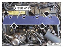
- Prepare the panel (1) from the special tool 2 358 417
with the spacer sleeves 2 455 172
.
NOTE:
RISK OF DAMAGE
Damage to injectors.
Excessive force may damage the injector and this means having to replace the injector.
Damage to injectors.
Excessive force may damage the injector and this means having to replace the injector.
- Do not use the puller plate as a support.
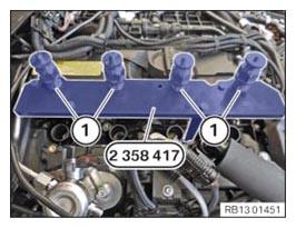
- Attach the special tool 2 358 417 with the spacer sleeves 2 455 172 on the cylinder head.
- Hand-tighten the bolts (arrows).
NOTE:
TECHNICAL INFORMATION
The extraction thread is a left-hand thread.
The extraction thread is a left-hand thread.
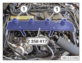
- Screw in pull-out thread (1) on the special tool 2 358 417
fully.
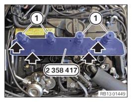
- Insert the threaded sleeves (1) again and screw threaded sleeves completely onto the intake for the injectors.
- Tighten the screws (arrows) on the special tool 2 358 417
to 5 Nm.
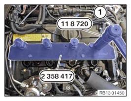
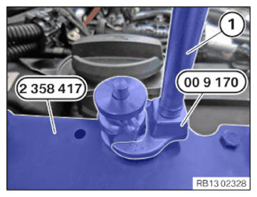
- Adjust the torque wrench (1) to 13 Nm clockwise rotation .
- Turn torque wrench (1) in clockwise direction with special tool 0 496 106 (11 8 720) until the injectors of cylinder 1, 3, 4 are pulled out.
NOTE:
TECHNICAL INFORMATION
If the torque wrench makes a crack when the injector is pulled out, the injector must be replaceed .
If the torque wrench makes a crack when the injector is pulled out, the injector must be replaceed .
- Disassemble all injectors individually.
- Adjust the torque wrench (1) to 13 Nm clockwise rotation .
- Turn torque wrench (1) in clockwise direction with special tool 0 490 507 (00 9 170) until the injector of cylinder 2 is pulled out.
NOTE:
TECHNICAL INFORMATION
If the torque wrench makes a crack when the injector is pulled out, the injector must be replaceed .
If the torque wrench makes a crack when the injector is pulled out, the injector must be replaceed .
- Disassemble all injectors individually.
- Before removing the special tool 2 358 417
with the injectors, check if all the injectors were completely pulled out of the cylinder head.
The threads of the pull-out thread must be completely visible.
- Loosen screws on special tool 2 358 417
.
- Carefully remove the special tool 2 358 417 with the injectors (1) vertically straight up from the cylinder head.
- Place the combination of the special tool 2 358 417 and the injectors (1) flat onto a clean table.
NOTE:
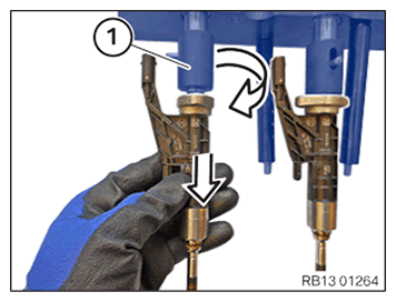
The description is for one component only. The procedure is identical for all further components.
- Unlock the stand lock (1) from the top.
- Turn the unlocked stand (1) by 90° .
- Release and remove the injector downwards.