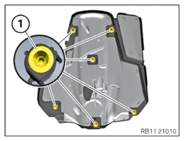
Installing the retaining bridge
Check
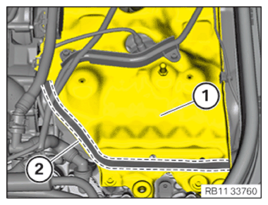
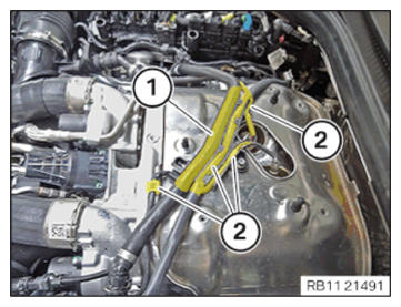
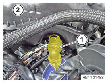
- Check if the foam seal on retaining bridge (1) in area (2) is damaged, porous, loose or present.
Result
» Foam seal (2) is damaged or porous or loose.
Measure
- Replace the foam seal (2).
Parts: foam
Measure
- Clean any foam seal residue or adhesive residue on the bonding surface in area (2) with cleaning agent R2.
Parts: Cleaning agent
Measure
- Bond foam seal (2).
Result
» Foam seal (2) is not installed.
Measure
- Retrofit foam seal (2).
Parts: foam
Measure
- Clean the bonding surface in area (2) with cleaning agent R2.
Parts: Cleaning agent
Measure
- Bond the foam with an adhesive.
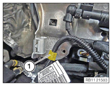
- Clip wiring harness mounting (1) into the retaining bridge.
- Clip wiring harness mounting (1) into the retaining bridge.
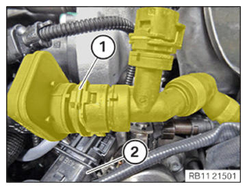
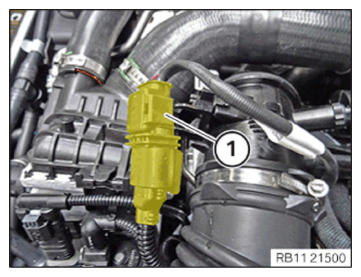
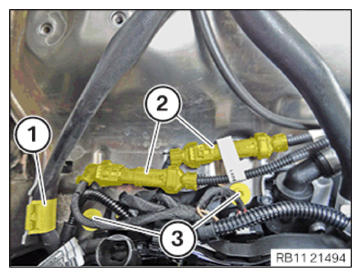
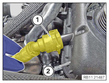
- Feed the connector (2) of the Lambda oxygen sensor through.
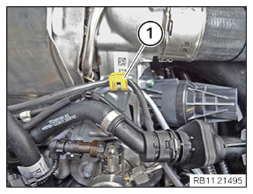
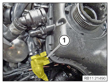
- Connect and lock the engine ventilation line to the retaining clip in the region of (1).
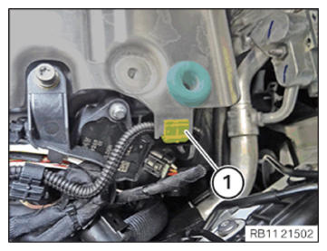
- Connect connectors (1) and lock.
- Clip in the cable from the Lambda oxygen sensor on the holder (1).
- Clip wiring harness mounting (1) into the retaining bridge.
- Feed the connector (2) of the Lambda oxygen sensor through.
- Connect and lock the engine ventilation line to the retaining clip in the region of (1).
- Connect connectors (1) and lock.
- Connect connectors (1) and lock.
- Clip In the cable from the Lambda oxygen sensor on the holder (1).
- Connect connectors (1) and lock.
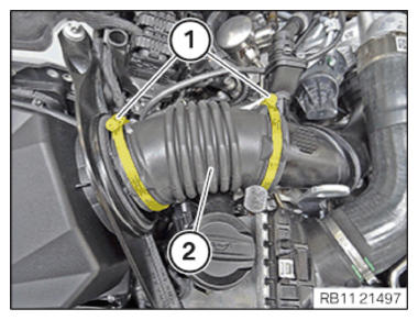
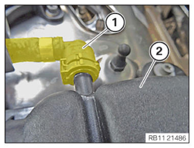
- Install bellows (2).
- Tighten hose clamp (1).TIGHTENING TORQUES SPECIFICATION
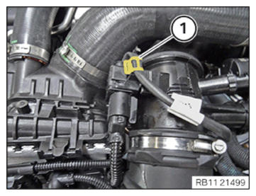
Hose clamp Hose clamp Tightening torque 3 Nm - Connect and lock the engine ventilation line to the retaining clip in the region of (1).
- Clip in the cable from the Lambda oxygen sensor on the holder (1).
- Clip in the connector (2) downwards in the heat shield.
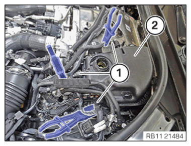
- Clip the transmission wiring harness on to the bracket (1).
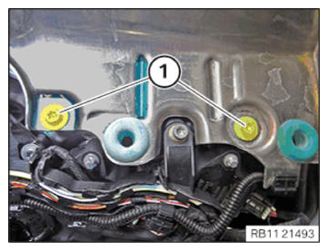
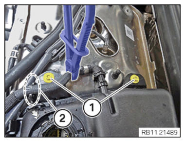
- Tighten down screws (1).TIGHTENING TORQUES SPECIFICATION
Support bridge M6x16 screw Tightening torque 10 Nm - Clip in the wiring harness from the attachment points (2).
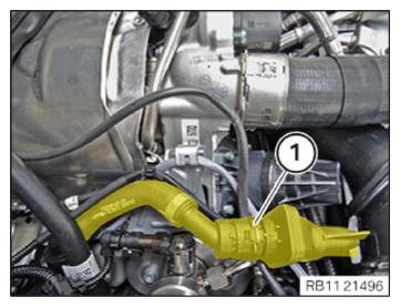
- Working downwards, clip in the engine ventilation line (1).
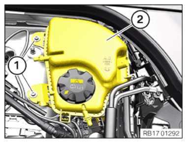
- Feed in and install coolant expansion tank (2).
- Tighten down screws (1).TIGHTENING TORQUES SPECIFICATION
Coolant reservoir M 6x20 screw Tightening torque 11 Nm - Connect the wiring harness mounting to the snap-in lug (1) and lock it.
- Tighten down screws (1).TIGHTENING TORQUES SPECIFICATION
Coolant reservoir M6x20 screw Tightening torque 11 Nm - Clip in the coolant line to the bracket in the region (2).
- Connect the coolant line (1) to the coolant expansion tank (2) and lock it.
- Connect the coolant line (1) to the coolant expansion tank (2) and lock it.
- Connect the coolant line (1) to the coolant expansion tank (2) and lock It.
- Use clamping pliers to remove the coolant hoses (1) from the coolant expansion tank (2).
- Connect connectors (1) and lock.
- Clip the wiring harness into the wiring harness mounting (1).
- Close the sealing cap (1) of the coolant expansion tank.
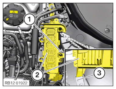
Installing the control unit bracket for cylinders 5 to 8:
NOTE: RISK OF DAMAGE
Electrostatic discharge.
Damage to or destruction of electrical components.- Leave the electrical components in their original packaging until they are being installed. Only use the original packaging for returning the product. Always package removed components straight away.
- Read and comply with user information on using the associated special tool 12 7 060.
- Only tap the housings of electrical components. Do not tap pins or multi-pin connectors directly.
- Wear electrically conductive clothing and antistatic shoes (with ESD symbol).
- For additional information see: 61 35... NOTES ON ESD (ELECTROSTATIC DISCHARGE) PROTECTION .
NOTE: TECHNICAL INFORMATION
Follow instructions for REMOVING AND INSTALLING CONTROL UNITS .NOTE: TECHNICAL INFORMATION
Disconnecting control units may cause fault code entries and functional limitations. Fault code entries must be read out and deleted if necessary. - Guide and install control unit bracket (2) with the DME control unit into holder (3).
- Tighten down screws (1).TIGHTENING TORQUES SPECIFICATION
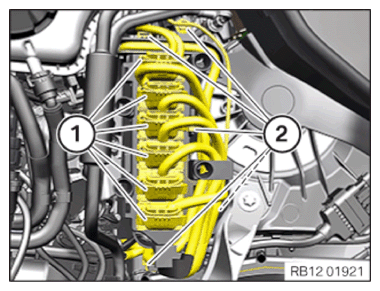
Control unit holder Hexagon screw Tightening torque 8 Nm - Fasten all the clamps (2).
- Connect all connectors (1) and lock.
The connectors (1) must engage audibly.
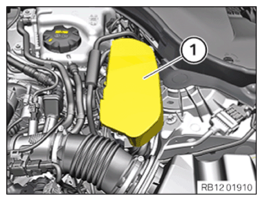
Installing the cover of the left DME control unit
- Feed in the cover (1) in the guides and install it.
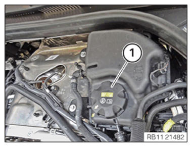
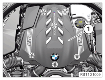
Installing acoustic cover
NOTE: RISK OF DAMAGE
Damage to the acoustic cover/design cover.
Jerky movements during disassembly and application of excessive force during installation may result in breakage of the acoustic cover/design cover.- Disassemble or mount the acoustic cover/design cover carefully.
- Disassemble or mount snap-lock couplings of the ball pivots one after the other.
- Disassemble or mount the acoustic cover/design cover only at temperatures > 20°C.
- Use only distilled water as an auxiliary material during installation, no lubricants.
- Check the rubber mount (1) for a correct seat of the acoustic cover.
- Install the acoustic cover (1) and fasten It In the rubber mounts (marks).
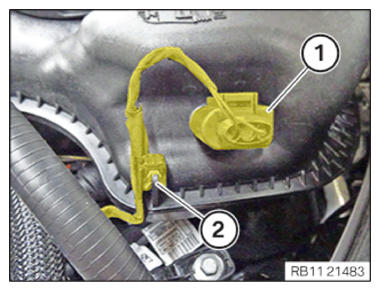
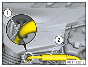
- Version with clip:
Clip In the tank vent line (2) Into the clamp (1).
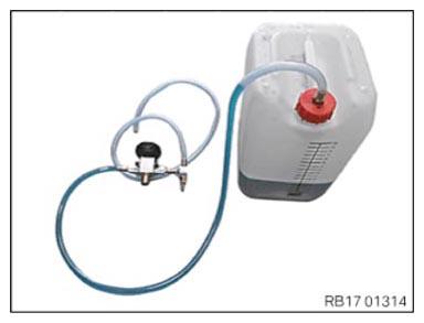
Fill and vent the high-temperature coolant circuit:
NOTE: TECHNICAL INFORMATION
It is mandatory to fill the cooling system before bleeding.
Fill both the circuits for high and low-temperature coolant circuits.