Installing upper oil sump section (engine removed)
NOTE:
RISK OF DAMAGE
Damage to the surface.
The use of metal-cutting tools (e.g., emery cloths) for cleaning surfaces can damage them and lead to leaks and/or engine damage.
Damage to the surface.
The use of metal-cutting tools (e.g., emery cloths) for cleaning surfaces can damage them and lead to leaks and/or engine damage.
- Do not use any metal-cutting tools.
NOTE:
RISK OF DAMAGE
Careless handling of tools and sharp-edged components. Scratches, surface damage.
Careless handling of tools and sharp-edged components. Scratches, surface damage.
- Protect working area.
- Handle tools and components carefully.
NOTE:
TECHNICAL INFORMATION
Clean all threaded belt connections with micro-encapsulated outer and internal threads.
Shavings or other debris must not remain in the components.
If a microencapsulated screw is reused, it must be coated with the following screw locking agent: Loctite 243, medium strength.
The screw connection must be completed within 10 minutes as hardening begins after this period.
- Clean all threads for attachment with a suitable screw tap M8 (1).NOTE: RISK OF DAMAGE
Damage to the surface.
The use of metal-cutting tools (e.g., emery cloths) for cleaning surfaces can damage them and lead to leaks and/or engine damage.- Do not use any metal-cutting tools.
- Clean sealing surface (1).NOTE: RISK OF DAMAGE
Damage to the surface.
The use of metal-cutting tools (e.g., emery cloths) for cleaning surfaces can damage them and lead to leaks and/or engine damage.- Do not use any metal-cutting tools.
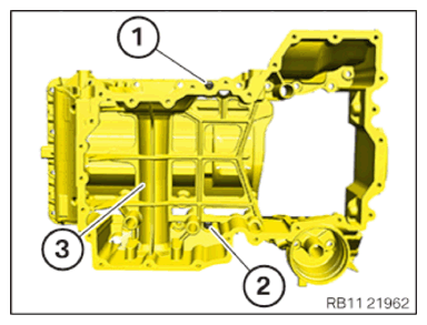
- Clean sealing surface (1).
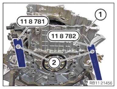
- Screw special tools 0496 121 (11 8 781) and 0496 120 (118 780) to the upper oil sump section (1) hand-tight.
- The special tools 0 496 121 (11 8 781)
and 0 496 120 (11 8 780)
must lie flat on the crankcase.
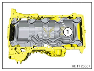
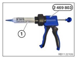
- Install sealant (1) as shown on the special tool 2 469 803. SEALING COMPOUND DESCRIPTION
Loctite 5970 liquid sealing compound Processing time <10 minutes at room temperature 50 ml, Cartridge 83190404517 NOTE: TECHNICAL INFORMATION
The sealing surfaces must be free of oil, grease and cleaning agents. - Apply the prescribed amount of sealant to the separation points in the marked area.
Using more than the recommended amount of sealant may result in leakage.
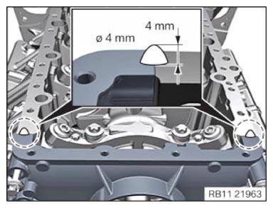
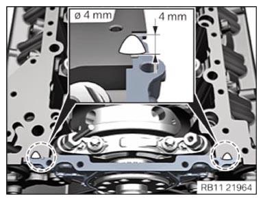
AMOUNT OF SEALING COMPOUND SPECIFICATIONHeight 4 mm Diameter 4 mm The sealing surfaces must be free of oil, grease and cleaning agents.
- Apply the prescribed amount of sealant to the separation points in the marked area.
Using more than the recommended amount of sealant may result in leakage.
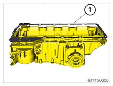
AMOUNT OF SEALING COMPOUND SPECIFICATIONHeight 4 mm Diameter 4 mm - Replace the seal (1).
Parts: Gasket
- Position seal (1) on upper oil sump section.NOTE: TECHNICAL INFORMATION
Microencapsulated screws must be replaced and may not be reused.
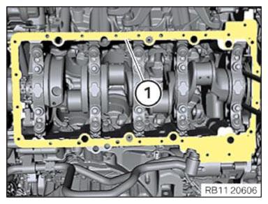
The screw lining must be completed within 10 minutes, as the hardening begins after this time period. Microencapsulated screws must not be retightened. - Position upper oil sump section (3) with the seal on the crankcase.
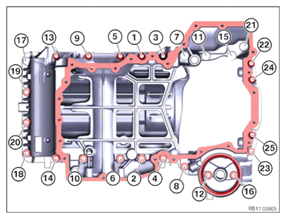
- Replace screws (1) and (2). Observe screw lengths.
Screws Installation location M8x25 1, 3, 4, 5, 7, 8, 9, 11, 12, 14, 15, 16, 17, 18, 19, 20 M8x45 2, 6, 10, 13, 21, 22, 23, 24, 25 - Tighten down screws (1) and (2).TIGHTENING TORQUES SPECIFICATION
Initial torque of upper oil sump section M8x25, M8x45 Replace screws. tightening torque 5 Nm NOTE: TECHNICAL INFORMATION
Microencapsulated screws must be replaced and may not be reused.
The screw lining must be completed within 10 minutes, as the hardening begins after this time period. Microencapsulated screws must not be retightened. - Replace screws (3) to (25). Observe screw lengths.
Screws Installation location M8x25 1, 3, 4, 5, 7, 8, 9, 11, 12, 14, 15, 16, 17, 18, 19, 20 M8x45 2, 6, 10, 13, 21, 22, 23, 24, 25 NOTE: TECHNICAL INFORMATION
When assembling, it is essential to observe screwing sequences and tightening torques.
Failure to comply with the regulations can lead to leaks and damage. - Tighten screws (1) to (25) in the screwing sequence.TIGHTENING TORQUES SPECIFICATION
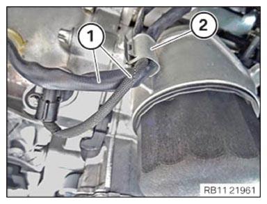
Oil sump upper section to crankcase M8x25, M8x45 Replace screws. 1. Joining torque 27 Nm 2. tightening torque 27 Nm - Secure cable (1) to the clamp (2).
- Secure clamp (arrow).
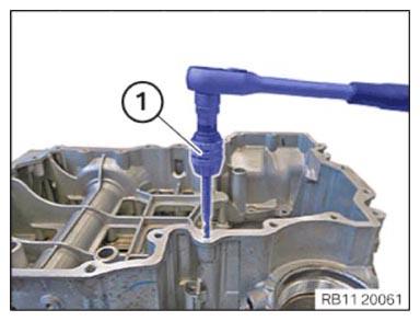
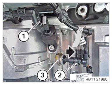
- Install and tighten the oil pressure sensor (3).TIGHTENING TORQUES SPECIFICATION
Oil pressure sensor M12x1.5 Tightening torque 15 Nm - Connect connectors (2) and lock.
The connector (2) must engage audibly.
- Connect connectors (1) and lock.
The connector (1) must engage audibly.