Blocking the camshafts
Check
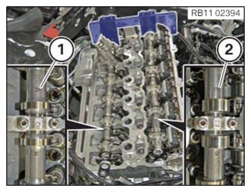
- Check whether the mark (1) of the exhaust camshaft and the mark (2) of the intake camshaft can be read from above.
Result
» Marks (1) and (2) cannot be read from the top.
Measure
- Turn the camshafts to the correct position or re-adjust the valve timing.
Check
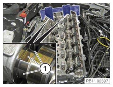
- Check whether the center of the three flattened areas (1) on both camshafts points upwards.
The special tool 2 358 122 can also be mounted if the camshafts are twisted by 180° (central flattened area points downwards).
Result
» The center of the three flattened areas (1) does not point upwards.
Measure
- Turn the camshafts to the correct position so that the center of the three flattened areas (1) on both camshafts points upwards.
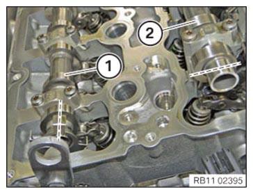
- Check whether the cam of the exhaust camshaft (1) and the intake camshaft (2) are positioned on the cylinder as shown.
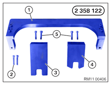
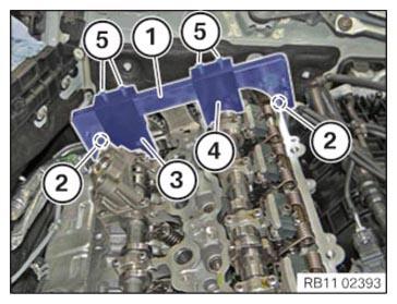
- The special tool 2 358 122
consists of multiple parts.
Number Description 1 Basic carrier 2 Basic carrier screws on cylinder head 3 Gauge to fix exhaust camshaft 4 Gauge to fix intake camshaft 5 Screw gauge on basic carrier - Fix basic carrier (1) of the special tool 2 358 122 with the bolts (2) to the cylinder head.
- Position gauge (3) with the recess on the exhaust camshaft and fix with the screws (5) on the basic carrier (1).
- Position gauge (4) with the recess on the intake camshaft and fix with the screws (5) on the basic carrier (1).NOTE: If the special tool 2 358 122 cannot be mounted, the valve timing must be readjusted.