Removing the retaining bridge in vehicles with a gasoline particulate filter
WARNING:
Hot surfaces.
Risk of burning!
Risk of burning!
- Perform all work only on components that have cooled down.
NOTE:
RISK OF DAMAGE
Injectors contaminated with coolant.
Damage to and failure of injectors that were coated with coolant for an extended period.
Injectors contaminated with coolant.
Damage to and failure of injectors that were coated with coolant for an extended period.
- Covering injectors with suitable auxiliary materials before testing or topping up the coolant is mandatory.
- Covering injectors with suitable auxiliary materials before working on the cooling system in the area of the injectors is mandatory.
- If necessary, draw off all of the coolant from the coolant expansion tank.
- Always clean injectors or injector shafts contaminated with coolant (e.g. with compressed air).
NOTE:
TECHNICAL INFORMATION
Collect and dispose of emerging fluids. Observe country-specific waste disposal regulations.
Collect and dispose of emerging fluids. Observe country-specific waste disposal regulations.
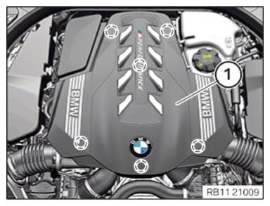
Removing the acoustic cover
NOTE:
RISK OF DAMAGE
Damage to the acoustic cover/design cover.
Jerky movements during disassembly and application of excessive force during installation may result in breakage of the acoustic cover/design cover.
Damage to the acoustic cover/design cover.
Jerky movements during disassembly and application of excessive force during installation may result in breakage of the acoustic cover/design cover.
- Disassemble or mount the acoustic cover/design cover carefully.
- Disassemble or mount snap-lock couplings of the ball pivots one after the other.
- Disassemble or mount the acoustic cover/design cover only at temperatures > 20°C.
- Use only distilled water as an auxiliary material during installation, no lubricants.
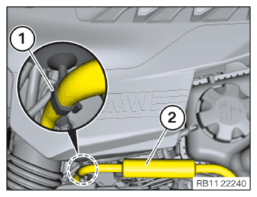
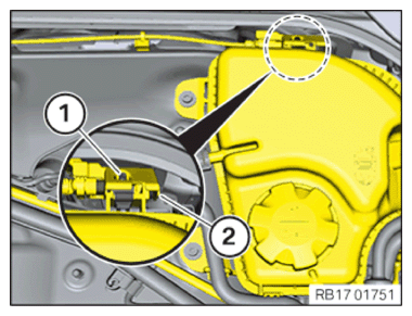
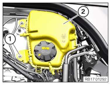
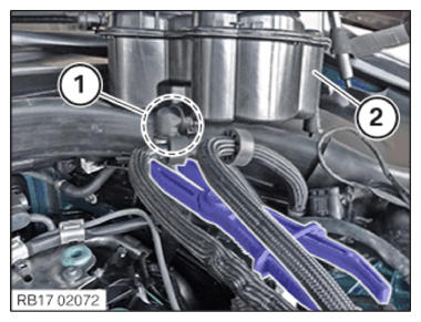
- Version with clip:
Unclip the tank vent line (2) at the clamp (1).
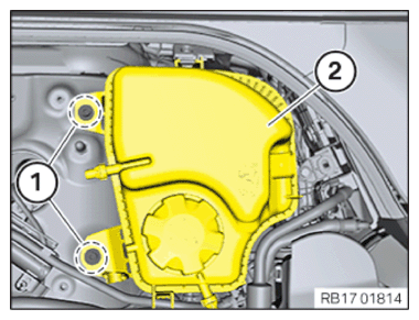
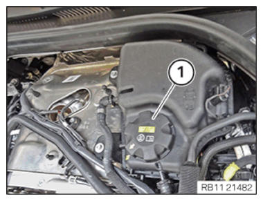
- Release the acoustic cover (1) upwards out of the rubber mounts (markings).
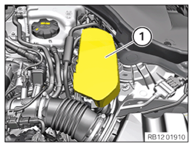
Removing the cover panel of the left DME control unit
- Remove the cover (1) and pull it up.
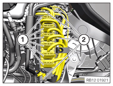
Removing the control unit bracket for cylinders 5 to 8
NOTE:
RISK OF DAMAGE
Electrostatic discharge.
Damage to or destruction of electrical components.
Electrostatic discharge.
Damage to or destruction of electrical components.
- Leave the electrical components in their original packaging until they are being installed. Only use the original packaging for returning the product. Always package removed components straight away.
- Read and comply with user information on using the associated special tool 12 7 060.
- Only tap the housings of electrical components. Do not tap pins or multi-pin connectors directly.
- Wear electrically conductive clothing and antistatic shoes (with ESD symbol).
- For additional information see: 61 35... NOTES ON ESD (ELECTROSTATIC DISCHARGE) PROTECTION .
NOTE:
TECHNICAL INFORMATION
Follow instructions for removing and installing control units.
For additional information see: NOTES ON REMOVAL AND INSTALLATION OF CONTROL UNITS .
Follow instructions for removing and installing control units.
For additional information see: NOTES ON REMOVAL AND INSTALLATION OF CONTROL UNITS .
NOTE:
TECHNICAL INFORMATION
Disconnecting control units may cause fault code entries and functional limitations. Fault code entries must be read out and deleted if necessary.
Disconnecting control units may cause fault code entries and functional limitations. Fault code entries must be read out and deleted if necessary.
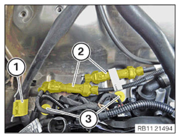
- Unlock and disconnect all plug connections (1).
- Disconnect all clamps (2).
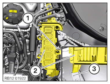
- Loosen screws (1).
- Guide out and remove control unit bracket (2) with the DME control unit upwards out of holder (3).
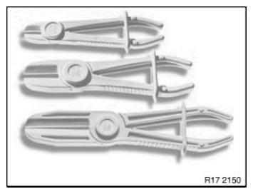
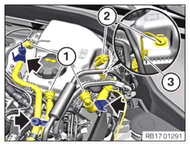
- Use commercially available disconnection tools to pinch off the coolant lines.
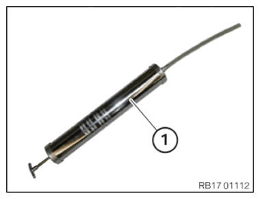
- Use commercially available syringe (1) or suitable tool to draw off coolant expansion tank.
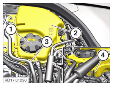
- Loosen sealing cap (1).
- Draw off coolant using standard pump from the coolant expansion tank (2) and dispose of it.
- Disconnect the coolant hose (3) from the coolant expansion tank (2).
- Unlock and loosen holder (4).
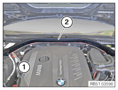
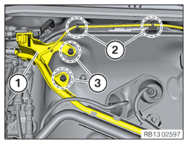
- Equipment specification with gasoline particulate filter:
Feed the cable (1) out of the brackets toward the front.
Detach the rear hood seal (2) inwards from the guide.
- Equipment specification with gasoline particulate filter:
- Loosen screws (1).
- Carefully slide the coolant expansion tank (2) upwards and to the front.
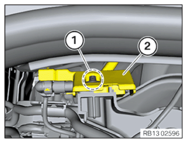
- Equipment specification with gasoline particulate filter:
Release the screws (1) several thread starts.
Lift the holder of the GPF (2) upward and out of the guide.
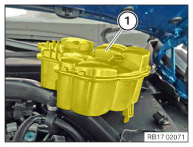
- Thread out coolant expansion tank (2) and remove.
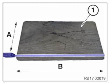
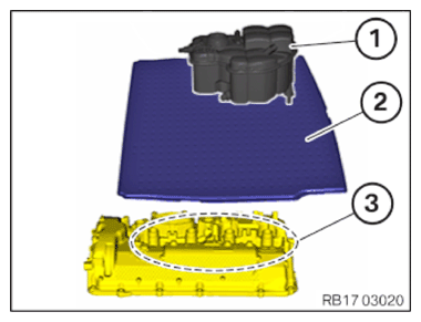
- Prepare a standard waterproof rubber mat (1).
| Letter: | Dimension in cm |
|---|---|
| A | 32.00 |
| B | 52.00 |
NOTE:
Schematic diagram is for example purposes. Some parts may differ in certain details.
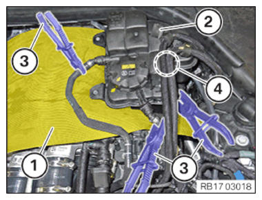
- Illustrated on the S63T4:
- Unclamp the coolant hoses with clamping pliers (3).
- Raise coolant expansion tank (2).
- Position the rubber mat (1) between the expansion tank and the cylinder head cover.
- Unclip the fuel lines in area (4) from expansion tank (2).
- Ensure that rubber mat (2) covers the areas between expansion tank (1) and the cylinder head cover in the area of injector shafts (3).
- Loosen screws (1).
- Thread out coolant expansion tank (2) and remove.
NOTE:
TECHNICAL INFORMATION
Only flexible hose pipes may be disconnected.
Only flexible hose pipes may be disconnected.
- Disconnect the coolant hoses (1) with standard disconnection tools (arrows).
- Unlock and release coolant line (1).
- Catch and dispose of escaping coolant.
- Unlock plug connection (2) and disconnect.
- Disconnect clamp (3).
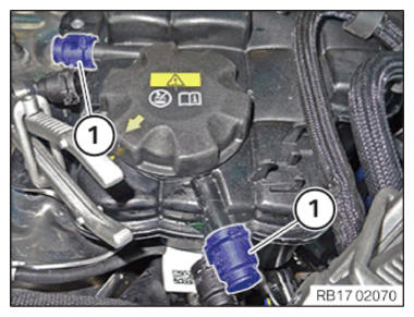
NOTE:
Schematic diagram is for example purposes. Some parts may differ in certain details.
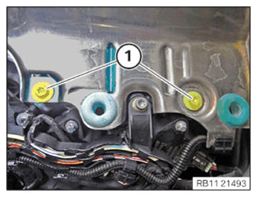
- Illustrated on the S63T4:
- Seal the connections to the coolant expansion tank with seal plugs (1) part number 17 12 8 515 062.
NOTE:
Schematic diagram is for example purposes. Some parts may differ in certain details.
- Illustrated on the S63T4:
- Set coolant expansion tank (1) aside.
NOTE:
Schematic diagram is for example purposes. Some parts may differ in certain details.
- Illustrated on the S63T4:
- Ensure that the coolant hose is clamped with clamping pliers.
- Unlock and disconnect coolant hose in area (1).
- Remove the coolant expansion tank (2).
NOTE:
RISK OF DAMAGE
Injectors contaminated with coolant.
Damage to and failure of injectors that were coated with coolant for an extended period.
Injectors contaminated with coolant.
Damage to and failure of injectors that were coated with coolant for an extended period.
- Covering injectors with suitable auxiliary materials before testing or topping up the coolant is mandatory.
- Covering injectors with suitable auxiliary materials before working on the cooling system in the area of the injectors is mandatory.
- If necessary, draw off all of the coolant from the coolant expansion tank.
- Always clean injectors or injector shafts contaminated with coolant (e.g. with compressed air).
CAUTION:
Swirling dirt particles caused by compressed air.
Injury hazard!
Injury hazard!
- Collect dirt particles, e.g. when blowing out, use cloth to do so.
- Wear safety goggles.
CAUTION:
Materials harmful to health.
Contact with fluids harmful to health!
Contact with fluids harmful to health!
- Note and follow safety instructions on containers.
- Conduct all work in appropriate personal protective equipment only.
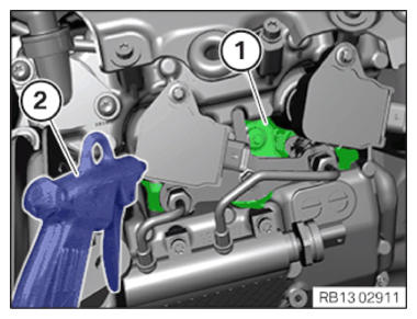
- Check the injector shafts for coolant residues (1).
- If there are coolant residues (1) in the injector shaft:
Clean the injector shafts with an air gun (2).
- Loosen the sealing cap (1) from the coolant expansion tank.
- Release screws (3).
- Release the wiring harness mountings (2).
- Set aside the holder (1) of the gasoline particulate sensor.
- Loosen screw (1).
- Slide the holder (2) of the gasoline particulate sensor with the gasoline particulate sensor to the rear.
- Unclip cable (1) of the Lambda oxygen sensor from the holder.
- Unclip wiring harness (2).
- Unclip intake line (3).
- Unclip the cable of the Lambda oxygen sensor from the bracket (4).
- Loosen screws (1).
- Unclip the transmission wiring harness from the bracket (1).
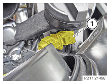
- Unclip the connector (2r) by pulling it up and out of the retaining bridge.
- Loosen screws (3).
- Unclip the Lambda oxygen sensor cable from the bracket (1).
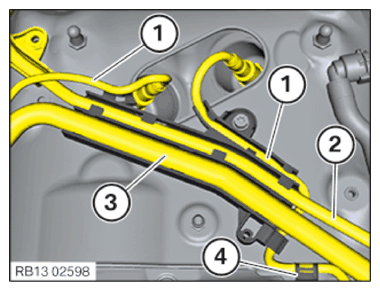
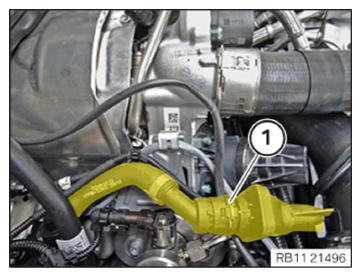
- Unlock and disconnect the engine ventilation line from the retaining clip in the region of (1).
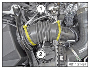
- Release the hose clamps (1).
- Remove the bellows (2).
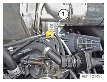
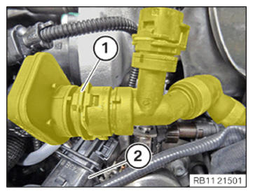
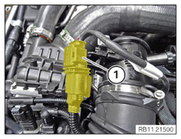
- Unlock plug connection (1) and disconnect.
- Unclip the Lambda oxygen sensor cable from the bracket (1).
- Unlock plug connection (1) and disconnect.
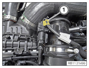
- Unlock and disconnect the engine ventilation line from the retaining clip in the region of (1).
- Connect the connector (2) of the Lambda oxygen sensor.
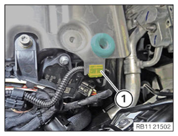
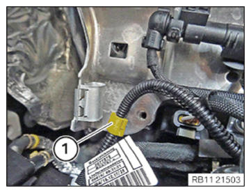
- Unclip the wiring harness mounting (1) from the retaining bridge.
- Unclip the wiring harness mounting (1) from the retaining bridge.
- Remove the retaining bridge upward.