Install the left high pressure pump
NOTE:
RISK OF DAMAGE
Contaminant or foreign body.
Contamination can result in malfunctions, loss of function or leaks.
Contaminant or foreign body.
Contamination can result in malfunctions, loss of function or leaks.
- Adhere to the utmost cleanliness.
- Protect components from contamination e.g. by covering.
- Close off line connections with seal plugs.
NOTE:
TECHNICAL INFORMATION
Collect and dispose of emerging fluids. Observe country-specific waste disposal regulations.
Collect and dispose of emerging fluids. Observe country-specific waste disposal regulations.
NOTE:
TECHNICAL INFORMATION
Only N63:
On vehicles with an active stabilizer (ARS), the fan cowl must be removed to crank the engine.
For additional information see: 17 11 035 REMOVING AND INSTALLING/REPLACING FAN COWL WITH ELECTRIC FAN .
Only N63:
On vehicles with an active stabilizer (ARS), the fan cowl must be removed to crank the engine.
For additional information see: 17 11 035 REMOVING AND INSTALLING/REPLACING FAN COWL WITH ELECTRIC FAN .
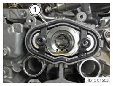
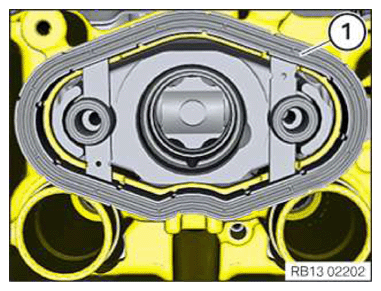
- Remove the seal (1).
- Check the threads (1) on the high pressure pump flange for sealing compound residue: Remove sealing compound residue as needed.
- Clean the thread (1).
- Make sure that no contamination enters the engine.
- Cover opening at the high pressure pump flange with suitable materials.NOTE: TECHNICAL INFORMATION
The sealing surfaces must be free of oil, grease and cleaning agents. - Clean sealing surface (1).
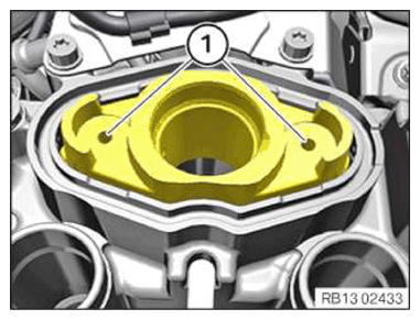
- Replace the high-pressure pump seal (1).
Parts: Gasket
- Remove residual screw sealant in the threaded holes on the high pressure pump bracket using compressed air.
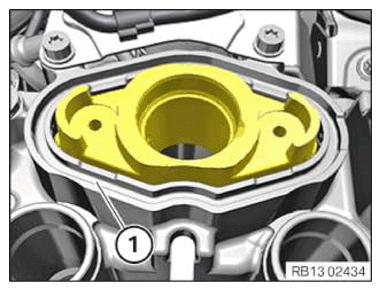
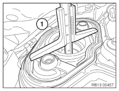
- Insert and install the gasket (1).
- Place the depth gauge (1) flat onto the high pressure pump flange.
- Turn the engine at the central bolt in the direction of the engine rotation until the depth gauge shows that the camshaft has reached the BDC position.NOTE: RISK OF DAMAGE
Damage to the engine.
If the engine is manually rotated in the wrong direction of rotation, the engine can be damaged.- Only rotate the engine manually in the correct direction of rotation: a) clockwise when looking at the damper, or b) counterclockwise when looking at the chain drive. b) applies only if the timing chain is installed in the rear.
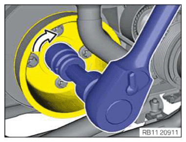
- Rotate the engine with the special tool in the direction of the arrow
until the cam of the high-pressure pump drive is at the BDC position
.
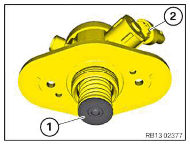
- Coat piston rest (1) of the high pressure pump (2) with engine oil.
Engine oil
Technically suitable engine oils for BMW Group engines
NOTE: TECHNICAL INFORMATION
The high pressure pump is preloaded by the piston spring and must be removed by alternately unscrewing the screws without tilting.
Before installing the high pressure pump, the cam of the high pressure pump drive must be turned to bottom dead center.
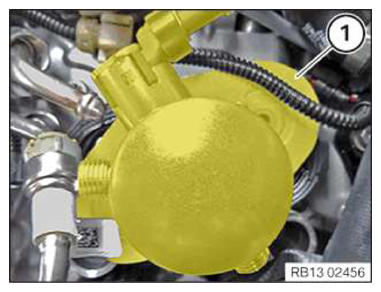
If necessary, turn the engine in the direction of engine rotation on the central bolt of the crankshaft, otherwise there is a risk of piston breakage of the high pressure pump. - Turn the high pressure pump (1) clockwise and position it.
- Feed in and install high pressure pump (2).
- Replace screws (1).
Parts: Screws
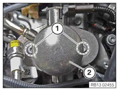
- Position the screws (1) on the high pressure pump (2) and tighten in alternating
order in steps of 90°
each.
Compliance with this specification is imperative to make sure that the piston will not break due to twisting.
TIGHTENING TORQUES SPECIFICATIONHigh-pressure pump to cylinder head M6
Replace screws.Tightening torque
11.8 Nm
Angle of rotation
90° - Tighten nut (1).TIGHTENING TORQUES SPECIFICATION
Fuel delivery line to high pressure pump M14 Tightening torque
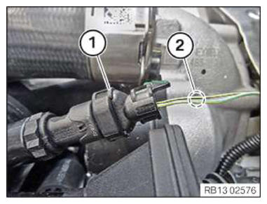
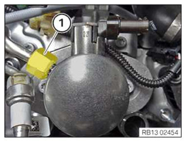
30 Nm - Connect plug connection (1) and lock.
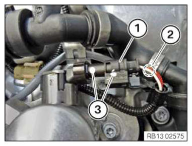
- Make sure that the connector of the high pressure pump (1) is not confused with the connector of the intake air temperature sensor.
- If there are no colored marks (3) on the plug connections of the high pressure pump: Attach the marks.
If necessary, identify the connector using the wiring diagram by means of cable colors in area (2).
- Make sure that the connector of the intake air temperature sensor (1) is not confused with the connector of the high pressure pump.
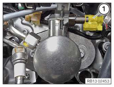
If necessary, identify the connector using the wiring diagram by means of cable colors in area (2).