Install auxiliary heater with holder
NOTE:
TECHNICAL INFORMATION
Collect and dispose of emerging fluids. Observe country-specific waste disposal regulations.
Collect and dispose of emerging fluids. Observe country-specific waste disposal regulations.
NOTE:
Schematic diagram is for example purposes. Some parts may differ in certain details.
NOTE:
TECHNICAL INFORMATION
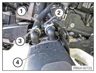
The coolant hoses are labeled 1 and 2. Position: 1 out (left), 2 in (right)
The coolant hoses are labeled 1 and 2. Position: 1 out (left), 2 in (right)
- Push the coolant hose (1) onto the left connection of the parked card heating (4) and fasten with the spring strap clamp (3).NOTE: TECHNICAL INFORMATION
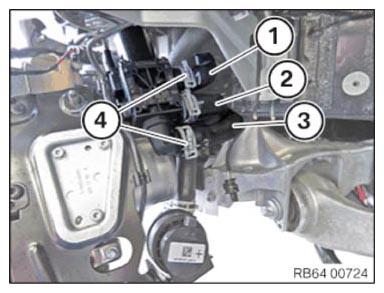
The coolant hoses are labeled either with Roman numerals I, II, III or with Arabic numerals 1, 2, 3. Position: I/1 top, II/2 middle, III/3 bottom. - Push the coolant hose (1) upwards and secure with the spring strap clamp (4).
- Push the coolant hose (3) downwards and secure with spring strap clamp (4).
- Catch and dispose of leakage coolant.
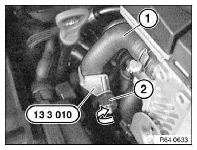
- Disconnect the special tool 0 491 256 (13 3 010)
. Screw the nut (2) in the direction of the arrow.
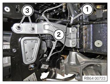
- Tighten nuts (3).
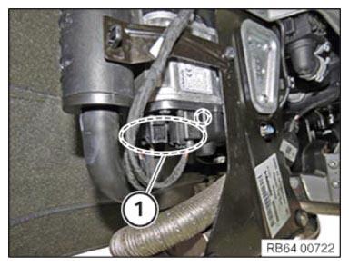
- Insert and connect the connector (2).
- Attach and connect the fuel line (1).
- Insert and connect all connectors (1).
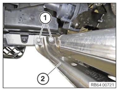
- Correctly position the holder (2) and tighten the screws (1).
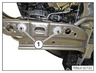
- Tighten nuts (1).