Installing the engine on the assembly stand
CAUTION:
Heavy component.
Heavy components can lead to injury or damage.
Heavy components can lead to injury or damage.
- Remove and install heavy components with the aid of another person/other persons.
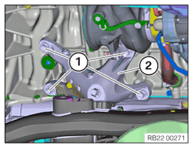
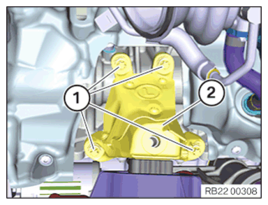
- Variant with rear wheel drive:
Loosen screws (1).
Remove the engine support bracket (2).
- Variant with all-wheel drive:
Loosen screws (1).
Remove the engine support bracket (2).
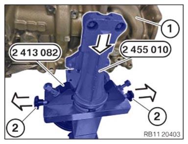
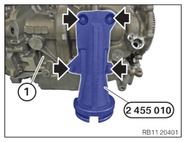
- Position the special tool 2 455 010 on the engine (1).
- Position and tighten the screws (arrows).
TIGHTENING TORQUE SPECIFICATIONS
| Special tool 2 455 010 to crankcase | ||
| M10x30 | Tightening torque | 38 Nm |
- Position the assembly jig 0 495 187 (00 2 300)
with the special tool 0 495 196 (00 2 320)
.
- Tighten the screws (arrows).
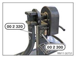
TIGHTENING TORQUE SPECIFICATIONS
| Special tool 00 2 320 to special tool 00 2 300 | ||
| M14X95 | Tightening torque | 130 Nm |
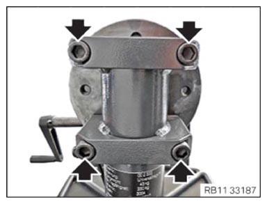
- Screw special tool 2 413 082 together with special tool 0 495 196 (00 2 320) .
- Tighten the screws (arrows).
TIGHTENING TORQUE SPECIFICATIONS
| Special tool 2 413 082 to special tool 00 2 320 | ||
| M12x65 | Tightening torque | 100 Nm |
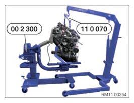
- Position the workshop crane with the special tool 0 490 579 (11 0 070)
and the engine on the special tool 0 495 187 (00 2 300)
.
- Detach the holder (2) in the direction of the arrow.
- Position the engine (1) with the special tool 2 455 010
in the direction of the arrow on the special tool 2 413 082
.
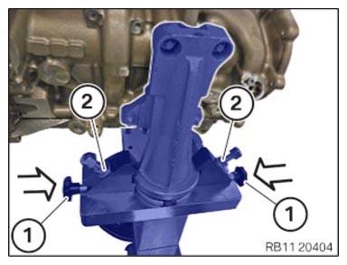
- Lock the holder (1) in the direction of the arrow.
- Tighten nuts (2).