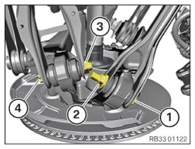
Attaching the camber control arm and trailing arm to the wheel carrier
- Replace the nuts (2) and (3) and screws (1) and (4).
Part: Nuts, bolts
- Position camber control arm on the wheel carrier.
- Insert the screws (4).
- Tighten nut (3).
TIGHTENING TORQUE SPECIFICATIONS
| Camber control arm to wheel carrier | ||
| M14 Replace screw and nut. |
Joining torque | 165 Nm |
| Angle of rotation | 90° | |
- Position trailing arm on the wheel carrier.
- Insert the screws (1).
NOTE:
TECHNICAL INFORMATION
Tighten the screw connection in the normal position.
Tighten the screw connection in the normal position.
- Tighten the nut (2) hand-tight.
The screw connection is tightened later in the NORMAL POSITION .