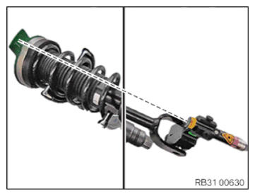
Aligning spring strut and spring strut support bearing to each other (AWD)
Injury hazard!
- Do not look into the laser beam.
Laser class 2 according to standard EN60825-1 (1994) P ≤ 1 mW
- During the installation, it is absolutely necessary
to align the installation position of the spring strut with the installation position of the spring strut support bearing using the special tools 2 210 778
and 2 450 246
.
This ensures a defined pre-tension at the screw connection of the spring strut fork at the bottom wishbone.
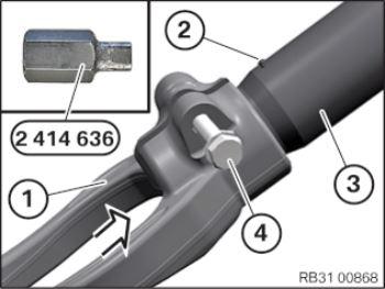
- Expand spring strut holder (1) with special tool 2 414 636
.
The spring strut holder (1) is required for aligning the spring strut support bearing.
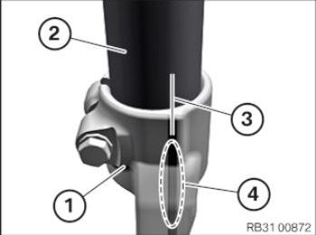
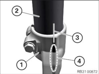
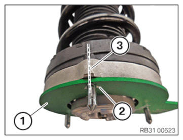
- Align spring strut holder 1 using the gap on the reference mark 2 on the spring strut 3.
- Position spring strut holder (1) on spring strut (3).
- Push spring strut holder (1) onto spring strut (3) to stop in arrow direction and align with color coding.
When replacing the spring strut, attach a color coding.
- Remove special tool 2 414 636 .
- Hand-tighten the bolt (4).
- Installation position of spring strut holder (1) relative to spring strut (2) must always
be checked on basis of available color coding (30 of vertical cut to elevation (4) and corrected if necessary.
- Observe the alignment of the spring strut fork (1).
Left spring strut (Illustration A): Stand for the anti-roll bar link (2) points from the top to the left.
Right spring strut (Illustration B): Stand for the anti-roll bar link (2) points from the top to the right.
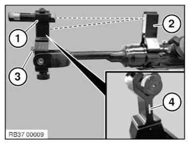
- Mount the laser (1) with the securing tool on the spring strut holder from the top.
- Place the mirror (2) vertical onto the spring strut!
- It is absolutely necessary
to set the mirror (2) onto a clean level surface!
Do not position the mirror (2) on labels or spot-welds!
The laser beam must face the mirror.
- Adjust the laser (1) with the adjustment screw (3) to project the laser beam via the mirror (2) to the mark (4).
- Remove the mirror (2).
The laser (1) can now no longer be adjusted (3) at the adjustment screw!
- Mount the 3 bolts to a special tool 2 450 246 (1).
- Align mark (2) on the special tool 2 450 246 (1) to mark (3) on the spring strut support bearing.
- Attach special tool 2 450 246
(1) on the spring strut support bearing.
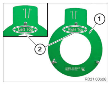
- Left spring strut:
The "Left Top" mark (2) can now be read from the top on the special tool 2 450 246 (1)!
- Right spring strut:
The "Right Top" mark (2) can now be read from the top on the special tool 2 450 246 (1)!
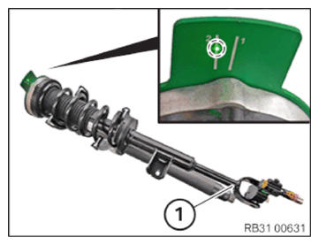
- Align spring strut (1) with the mark on special tool 2 450 246
on the spring strut support bearing using a laser beam.
Mark on the special tool 2 450 246: