Replace both air filter inserts
Prerequisite
- Ignition is switched off.
Preliminary work
- Remove the acoustic COVER .
- Remove the top engine compartment COVER .
- Remove the top right engine compartment COVER .
- Remove the left DME control unit COVER PANEL .
- Remove the right DME control unit COVER .
→ Removing the left air filter insert
Prerequisite
Ignition is switched off.
NOTE:
RISK OF DAMAGE. Damage to the clean air line. Damage to the air filter. For changing the air filter insert, if the upper section of intake filter housing is only raised and not completely removed, the clean air line and the air filter insert may be damaged.
- Do not lift upper section of intake filter housing by force.
- Unfasten clamp.
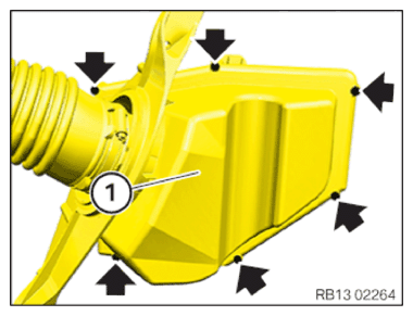
- Remove upper section of intake filter housing completely.
NOTE:
RISK OF DAMAGE. Use of an incorrect tool (impact screwdriver) to release and tighten the screws. Damaged thread.
- Only use a standard tool (e.g. reversible ratchet) to release/tighten the screws.
- If fitted:
Loosen screws (1).
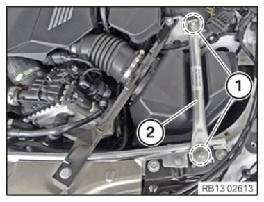
Remove strut (2).
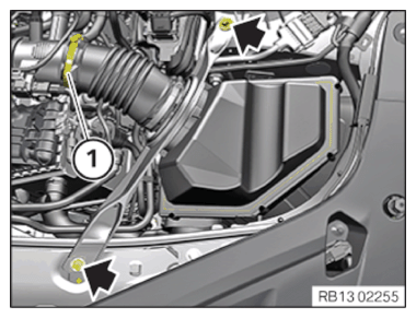
- Unfasten snap ring (1).
- Remove screws (arrows).
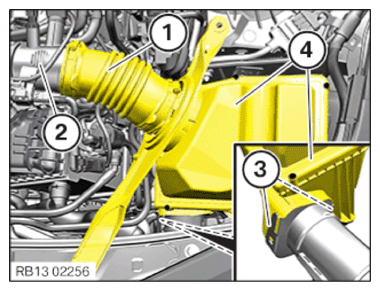
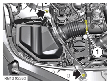
- Disconnect the upper section (1) of the clean air pipe from the lower part (2) of the clean air pipe.
- Unlock the locks (3).
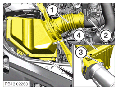
- Feed out left intake filter housing (4) to the top and remove.
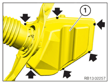
- Remove screws (arrows).
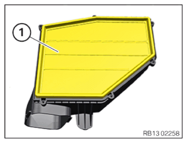
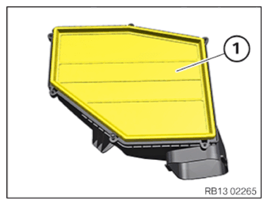
- Remove the upper section of the intake filter housing (1).
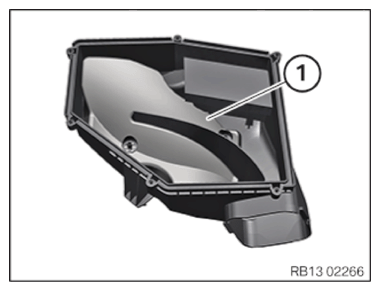
- Remove the air filter insert (1).
→ Removing the right air filter insert
Prerequisite
Ignition is switched off.
NOTE:
RISK OF DAMAGE. Damage to the clean air line. Damage to the air filter. For changing the air filter insert, if the upper section of intake filter housing is only raised and not completely removed, the clean air line and the air filter insert may be damaged.
- Do not lift upper section of intake filter housing by force.
- Unfasten clamp.
- Remove upper section of intake filter housing completely.
NOTE:
RISK OF DAMAGE. Use of an incorrect tool (impact screwdriver) to release and tighten the screws. Damaged thread.
- Only use a standard tool (e.g. reversible ratchet) to release/tighten the screws.
- If fitted:
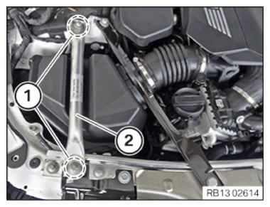
Loosen screws (1).
- Remove strut (2).
- Unfasten clamp (1).
- Remove screws (arrows).
- Disconnect upper section (1) of the clean air pipe from lower section (2) of the clean air pipe.
- Unlock the locks (3).
- Thread out and remove right intake filter housing (4) towards top.
- Remove screws (arrows).
- Remove the upper section of the intake filter housing (1).
- Remove the air filter element (1).
→ Installing the right air filter insert
NOTE:
RISK OF DAMAGE. Damage to the clean air line. Damage to the air filter. For changing the air filter insert, if the upper section of intake filter housing is only raised and not completely removed, the clean air line and the air filter insert may be damaged.
- Do not lift upper section of intake filter housing by force.
- Unfasten clamp.
- Remove upper section of intake filter housing completely.
- Insert and install the upper section of the intake filter housing (1).
- Tighten screws (arrows).
TIGHTENING TORQUES SPECIFICATION
| Intake filter housing upper section to intake filter housing lower section | ||
| Self-tapping bolt | Tightening torque | 2.4 Nm |
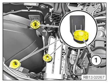
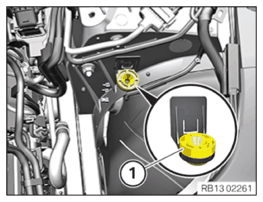
- Check the rubber mount (1) for correct fit.
- Insert and install the intake filter housing (4) on the right.
- Make sure that locks (3) lock correctly.
- Connect upper section (1) of the clean air pipe with the lower section (2) of the clean air pipe.
- Replace the bolts (arrows).
Parts: Screws
- Tighten screws (arrows).
TIGHTENING TORQUES SPECIFICATION
| Tension strut/Front-end strut to shock tower | ||
| External Torx socket M10X45 Replace screws. |
Joining torque | 56 Nm |
| Angle of rotation | 90° | |
TIGHTENING TORQUES SPECIFICATION
| Tension strut/Front-end strut, front | ||
| Hexagon screw M8X35 Replace screws. |
Joining torque | 28 Nm |
| Angle of rotation | 90° | |
- Tighten clamp (1).
TIGHTENING TORQUES SPECIFICATION
| Upper clean air pipe to lower clean air pipe | ||
| Hose clamp | Tightening torque | 3 Nm |
- If fitted:
Install strut (2).
- Tighten the screws (1).
→ Installing the left air filter insert
NOTE:
RISK OF DAMAGE. Damage to the clean air line. Damage to the air filter. For changing the air filter insert, if the upper section of intake filter housing is only raised and not completely removed, the clean air line and the air filter insert may be damaged.
- Do not lift upper section of intake filter housing by force.
- Unfasten clamp.
- Remove upper section of intake filter housing completely.
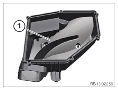
- Clean inside of lower section of intake filter housing (1).
- Install the air filter insert (1).
- Insert and install the upper part of the intake filter housing (1).
- Tighten the screws (arrows).
TIGHTENING TORQUES SPECIFICATION
| Intake filter housing upper section to intake filter housing lower section | ||
| Self-tapping bolt | Tightening torque | 2.4 Nm |
- Check the rubber mount (1) on the lower section of intake filter housing (2) for correct fit.
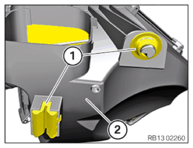
- Check rubber mount (1) for correct fit.
- Insert and install the intake filter housing (4) at left.
- Make sure that the locking mechanisms (3) lock correctly.
- Connect the upper section (1) of the clean air pipe with the lower section (2) of the clean air pipe.
- Replace the bolts (arrows).
Parts: Screws
- Tighten the screws (arrows).
TIGHTENING TORQUES SPECIFICATION
| Tension strut/Front-end strut to shock tower | ||
| External Torx socket M10X45 Replace screws. |
Joining torque | 56 Nm |
| Angle of rotation | 90° | |
TIGHTENING TORQUES SPECIFICATION
| Tension strut/Front-end strut, front | ||
| Hexagon screw M8X35 Replace screws. |
Joining torque | 28 Nm |
| Angle of rotation | 90° | |
- Tighten clamp (1).
TIGHTENING TORQUES SPECIFICATION
| Upper clean air pipe to lower clean air pipe | ||
| Hose clamp | Tightening torque | 3 Nm |
- If fitted:
Install the strut (2).
- Tighten the screws (1).
Follow-up work