Remove high-voltage battery unit
WARNING:
High-voltage system.
The high-voltage system operates on the basis of hazardous, electrical voltage and high currents. Mortal hazard through electric shock!
The high-voltage system operates on the basis of hazardous, electrical voltage and high currents. Mortal hazard through electric shock!
- All work on the high-voltage system may only be carried out by specially trained and technically experienced personnel.
- For additional Information see: 61 00... SAFETY INSTRUCTIONS on handling hybrid cars
- For additional Information see: 61 25... Notes on REPAIR of high-voltage battery unit
Preliminary work
- Suction the AIR CONDITIONING
- Remove luggage compartment trim panel right FLAP .
- De-energize the HIGH-VOLTAGE SYSTEM .
- CHECK that no voltage is applied.
- Remove rear UNDERBODY PROTECTION .
- Remove the transmission on the side UNDERBODY PLANKING
- Remove the tunnel connect SUPPORT
- Remove the rear axle COVER .
- Remove left and right tank COVER .
- Remove TORSION STRUT .
- Remove complete EXHAUST SYSTEM .
- Remove the HEAT SHIELDS .
- Completely remove the PROP SHAFT (plug-in - rear flexible disc).
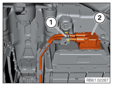
- Loosen the tension relief (1).
- Disconnect high-voltage connector (2).
Handling refrigerant lines
- Seal all components and lines in refrigerant circuit as well as return delivery parts immediately after disassembling with the special tool 0 494 179 (32 1 270), to prevent any ingress of moisture or foreign bodies.
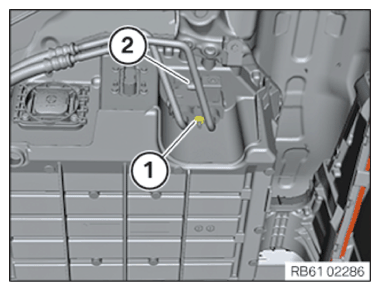
- Loosen the refrigerant line (1).
- Unlock plug connection (2) and disconnect.
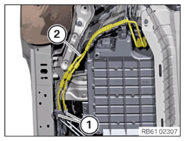
- Release the screws (1) on the refrigerant line (2).
- Remove the refrigerant line (2).
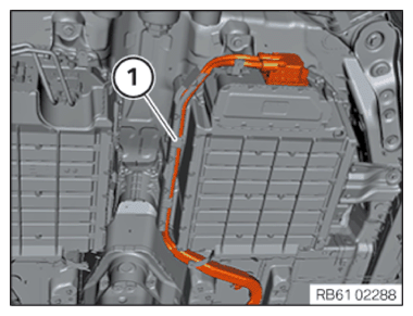
- Unclip the high-voltage cable (1).
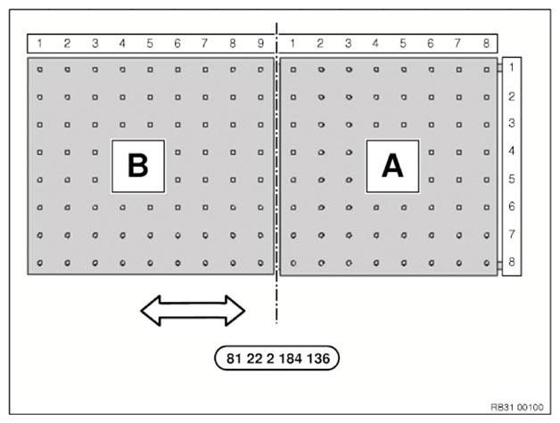
Fitting lifting table
- Always start coordinate determination at the top.
Sourcing reference for the MHT 1200 lifting table:
Seethe applicable BMW Parts Catalog pn 81222184136
The mobile lifting table MHT 1200 has three stands 80.
Additional stand 80: Order number: 81222357071
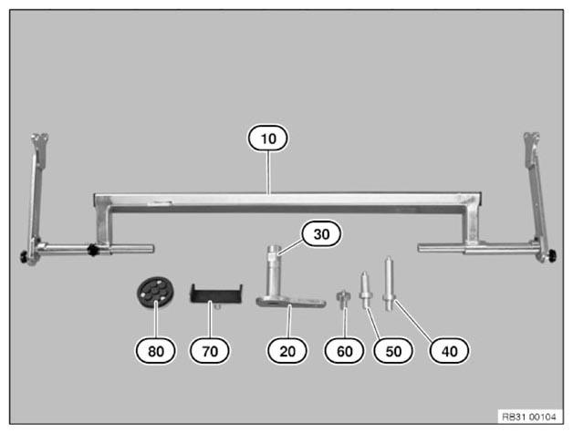
- The following tools are required to fit the lifting table:
Tool number: Number: 20 8 80 6 50 2 - Correctly prepare lifting table.
Proceed as follows for this:
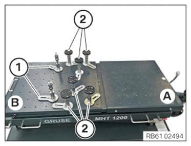
- Position the mounting element 20 with the stand 50 on the table top (B) for the high-voltage battery unit at coordinates 4/2 and 4/7 (1).
- Position the mounting elements 20
with the stands 80
on table top (B) for the high-voltage battery unit at coordinates 7/1, 9/2, 7/4, 5/8, 7/6 and 9/7 (2).
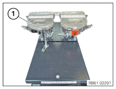
- Position the lifting table below the high-voltage battery unit (1).
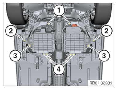
- Loosen screws (1).
- Loosen screws (2).
- Loosen screws (3).
- Loosen screws (4).
- Slowly lower the high-voltage battery unit with the lifting table.