Installing the mechatronics
NOTE:
RISK OF DAMAGE
Damage to the automatic transmission after removal of the mechatronics.
Serious damage to the automatic transmission due to non-compliance with the following tasks:
Damage to the automatic transmission after removal of the mechatronics.
Serious damage to the automatic transmission due to non-compliance with the following tasks:
- Load specific data status with the diagnostic system using an appropriate scan tool.
- Use only approved TRANSMISSION OIL .
- After completion of repair work, check the transmission OIL LEVEL .
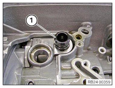
- Replace pressure pipe.
Parts: Pressure pipe
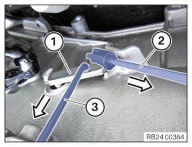
- Install pressure pipe (1).
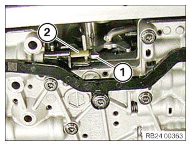
- Fit mechatronics unit.
- Feed shifting claw (1) into gearshift shaft (2).
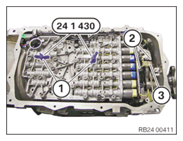
- Install mechatronics.
- Tighten wing nuts (1) of the special tool 0 496 715 (24 1 430) alternately until the mechatronics is
applied to the transmission.
- Position the screws (1) and slightly tighten.
- Pull the selector shaft tappet (1) downward with the special tool 2 355 850 (3) in the arrow direction.
- Remove the special tool 2 355 850 (2) in the direction of the arrow.
NOTE:
TECHNICAL INFORMATION
Note the original installation position of the output RPM sensor.
Observe the correct installation position when installing the output RPM sensor.
Note the original installation position of the output RPM sensor.
Observe the correct installation position when installing the output RPM sensor.
NOTE:
TECHNICAL INFORMATION
The tappet on the output RPM sensor may break off during removal or installation.
The tappet on the output RPM sensor may break off during removal or installation.
- Attach output RPM sensor (3) carefully and slide onto the stop.
- Position the screws (2) and slightly tighten.
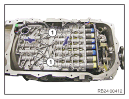
- Loosen wing nuts.
- Remove special tool 0 496 715 (24 1 430) .
- Position the screws (1) and slightly tighten.
- Replace the sealing sleeve (1).
Parts: Sealing sleeve
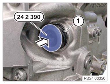
- Carefully insert the sealing sleeve (1).
The lug must be in the inner surface.
- Twist the sealing sleeve (1) until the lug has been inserted into the groove of the gear.
- Slide in sealing sleeve (1) up to the stop.
The lug on the sealing sleeve must not be damaged!
- Remove special tool 0 494 213 (24 2 390)
.
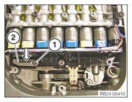
- Lock the sealing sleeve with the slide (2).
- Position the screw (1) and slightly tighten.
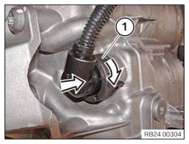
- Insert the connector (1) in the direction of arrow.
- Lock the connector (1) by turning the direction of arrow.
- Replace screws.
Parts: screw
NOTE:
TECHNICAL INFORMATION
When assembling, it is essential to observe screwing sequences and tightening torques.
Non-compliance with the regulations can lead to damage.
When assembling, it is essential to observe screwing sequences and tightening torques.
Non-compliance with the regulations can lead to damage.
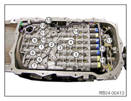
- Tighten screws in the order (1) to (17).
TIGHTENING TORQUES SPECIFICATION
| Mechatronics to transmission | ||
|---|---|---|
| M6x59, M6x20 Replace screws. |
Tightening torques | 8 Nm |
TIGHTENING TORQUES SPECIFICATION
| Output RPM sensor to transmission (position 17) | ||
|---|---|---|
| M6x20 Replace screw. |
Joining torque | 4 Nm |
| Angle of rotation | 12° | |
Follow-up work
- Install the oil volume RESERVOIR (GA8HP50Z, GA8HP51Z, GA8HP75Z, GA8HP76Z, GA8HP95Z).
- Install the transmission OIL PAN (GA8HP50Z, GA8HP51Z, GA8HP75Z, GA8HP76Z).
- Reconnect all battery GROUND LEADS .
- Check/top up the automatic transmission OIL LEVEL .
- Install rear UNDERBODY PROTECTION .
- Install the transmission side UNDERBODY PLANKING .
- Activate the 48 v ELECTRICAL SYSTEM .