Removing the mechatronics
NOTE:
DANGER
High-voltage system.
The high-voltage system operates on the basis of hazardous, electrical voltage and high currents. Mortal hazard through electric shock!
High-voltage system.
The high-voltage system operates on the basis of hazardous, electrical voltage and high currents. Mortal hazard through electric shock!
- All work on the high-voltage system may only be carried out by specially trained and technically experienced personnel.
- For additional information see: 61 00... SAFETY INSTRUCTIONS on handling hybrid cars
- For additional information see: 61 25... NOTES on repair of high-voltage battery unit
NOTE:
TECHNICAL INFORMATION
Zero voltage (high-voltage system switched-off) is only displayed with in PAD mode.
Zero voltage (high-voltage system switched-off) is only displayed with in PAD mode.
Preliminary work
- Remove right flap in luggage compartment TRIM PANEL .
- De-energize the HIGH-VOLTAGE SYSTEM .
- CHECK that no voltage is applied.
- Disconnect all battery GROUND LEADS .
- Remove the transmission side UNDERBODY PLANKING
- Remove rear UNDERBODY PROTECTION .
- Remove transmission CROSS-MEMBER .
- Remove transmission OIL PAN (all-wheel drive vehicle) (GA8HP75HZ).
- Remove the automatic transmission OIL PUMP (GA8HP75HZ).
CAUTION:
Materials harmful to health.
Contact with fluids harmful to health!
Contact with fluids harmful to health!
- Note and follow safety instructions on containers.
- Conduct all work in appropriate personal protective equipment only.
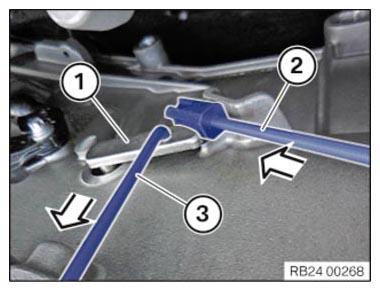
- Pull the selector shaft tappet (1) downward with the special tool 2 355 850 (3) in the direction of the arrow.
- Install the special tool 2 355 850
(2) between the selector shaft tappet (1) and transmission housing in arrow direction.
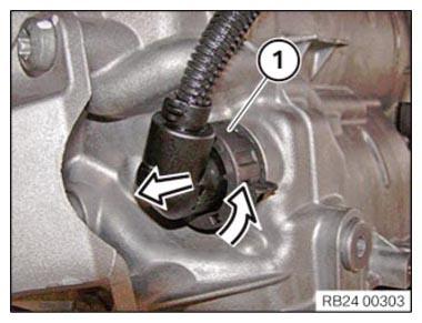
- Turn connector (1) in arrow direction and detach.
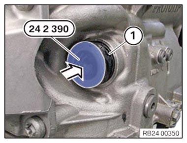
- Insert special tool 0 494 213 (24 2 390)
in sealing sleeve (1).
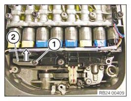
- Release the screw (1) and unlock the sealing sleeve with the slide (2) in arrow direction.
- Observe the installation position of the sealing sleeve (1).
The sealing sleeve (1) must be installed in the same position during installation.
- Pull out the sealing sleeve (1) in direction of the arrow.
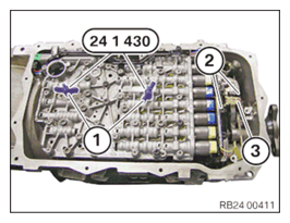
- Release the screws from the mechatronics in the marked area (1).
- Install the special tool 0 496 715 (24 1 430) in the marked area (1).
- Tighten the wing nuts (1).
- Loosen screws (2).NOTE: TECHNICAL INFORMATION
The tappet on the output RPM sensor may break off during removal or installation.NOTE: TECHNICAL INFORMATION
Note the original installation position of the output RPM sensor.
Observe the correct installation position when installing the output RPM sensor. - Carefully pull the output RPM sensor (3) out of the housing and insert it in the recess on the module.
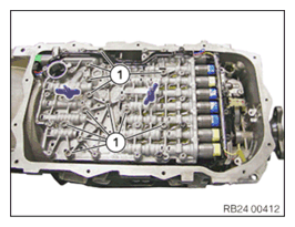
- Loosen screws (1).
- Remove the wing nuts of special tool 0 496 715 (24 1 430)
.NOTE: TECHNICAL INFORMATION
Carefully remove mechatronics. - Remove mechatronics.
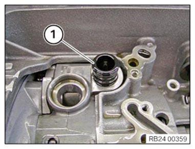
- Remove pressure pipe (1).