Removing the crankshaft sensor
Risk of burning!
- Perform all work only on components that have cooled down.
Damage to the acoustic cover/design cover.
Jerky movements during disassembly and application of excessive force during installation may result in breakage of the acoustic cover/design cover.
- Disassemble or mount the acoustic cover/design cover carefully.
- Disassemble or mount snap-lock couplings of the ball pivots one after the other.
- Disassemble or mount the acoustic cover/design cover only at temperatures > 20°C.
- Use only distilled water as an auxiliary material during installation, no lubricants.
Electrostatic discharge.
Damage to or destruction of electrical components.
- Leave the electrical components in their original packaging until they are being installed. Only use the original packaging for returning the product. Always package removed components straight away.
- Read and comply with user information on using the associated special tool 12 7 060.
- Only tap the housings of electrical components. Do not tap pins or multi-pin connectors directly.
- Wear electrically conductive clothing and antistatic shoes (with ESD symbol).
- For additional information see: NOTES ON ESD (ELECTROSTATIC DISCHARGE) PROTECTION .
Damage to the acoustic cover/design cover.
Jerky movements during disassembly and application of excessive force during installation may result in breakage of the acoustic cover/design cover.
- Disassemble or mount the acoustic cover/design cover carefully.
- Disassemble or mount snap-lock couplings of the ball pivots one after the other.
- Disassemble or mount the acoustic cover/design cover only at temperatures > 20°C.
- Use only distilled water as an auxiliary material during installation, no lubricants.
Risk of burning!
- Perform all work only on components that have cooled down.
Electrostatic discharge.
Damage to or destruction of electrical components.
Leave the electrical components in their original packaging until they are being installed. Only use the original packaging for returning the product. Always package removed components straight away.
Read and comply with user information on using the associated special tool 12 7 060.
Only tap the housings of electrical components. Do not tap pins or multi-pin connectors directly.
Wear electrically conductive clothing and antistatic shoes (with ESD symbol).
For additional information see: NOTES ON ESD (ELECTROSTATIC DISCHARGE) PROTECTION .
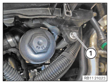
Loosen screw (1).
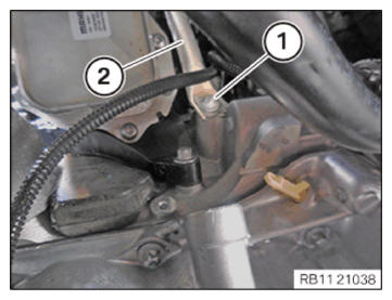
Loosen screw (1).
Guide out and remove the manifold bracket (2).
With automatic transmission:
Loosen screw (1).
Guide out and remove holder (2).
Loosen screw (3).
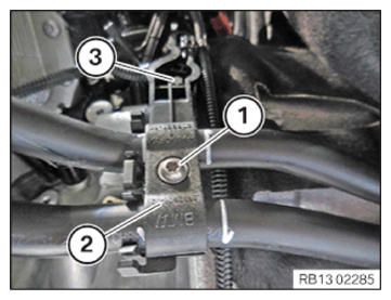
With automatic transmission:
Loosen clamp (1).
Feed out holder (2) from the guide (3).
Feed out and remove bracket (2) from the transmission oil lines (4).
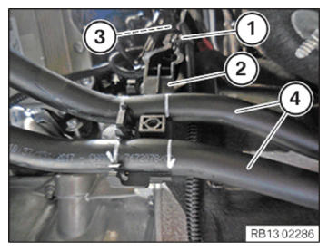
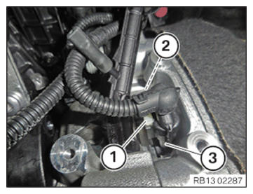
Unlock plug connection (1) and disconnect.
Loosen screw (2).
Guide out and remove crankshaft sensor (3).
Installing the crankshaft sensor
Feed in and install the crankshaft sensor (3).
Tighten down screw (2).
Connect connectors (1) and lock.
The connector (1) must engage audibly.
With automatic transmission:
Insert and install the holder (2).
Make sure that the holder (2) is installed correctly in the guide (3).
Position transmission oil line (4) on holder (2).
Secure clamps (1).
With automatic transmission:
Tighten down screw (3).
| Holder on end cover | ||
| M6X16 | Tightening torque | 8 Nm |
Insert and position the holders (2).
Tighten down screw (1).
| Holder for transmission oil line | ||
| Screw | Tightening torque | 4 Nm |
Guide in and position manifold support (2).
Hand-tighten the bolts (1).
Tighten down screws (1).
| Manifold bracket on intake plenum | ||
| M6x25 | tightening torque | 8 Nm |
Tighten screws (1) at the manifold brackets (2).
| Manifold bracket to crankcase | ||
| M6x16 | tightening torque | 8 Nm |
Preliminary work
- Refer to REMOVING THE ACOUSTIC COVER .
- Refer to REMOVING REAR UNDERBODY PROTECTION .
- Refer to REMOVING THE STIFFENING PLATE .
Electrostatic discharge.
Damage to or destruction of electrical components.
- Leave the electrical components in their original packaging until they are being installed. Only use the original packaging for returning the product. Always package removed components straight away.
- Read and comply with user information on using the associated special tool 12 7 060.
- Only tap the housings of electrical components. Do not tap pins or multi-pin connectors directly.
- Wear electrically conductive clothing and antistatic shoes (with ESD symbol).
- For additional information see: NOTES ON ESD (ELECTROSTATIC DISCHARGE) PROTECTION .
- Loosen screw (1).
- Loosen screw (1).
- Guide out and remove the manifold bracket (2).
- With automatic transmission:
Loosen screw (1).
Guide out and remove holder (2).
Loosen screw (3).
- With automatic transmission:
Loosen clamp (1).
Feed out holder (2) from the guide (3).
- Feed out and remove bracket (2) from the transmission oil lines (4).
- Unlock plug connection (1) and disconnect.
- Loosen screw (2).
- Guide out and remove crankshaft sensor (3).