Installing Lambda oxygen sensor
NOTE:
TECHNICAL INFORMATION
Grease the threads of new oxygen sensors thinly and evenly.
For oxygen sensors that are reused, the following should be observed:
Thinly and evenly grease the oxygen sensor on the thread only. Do not clean the part of the oxygen sensor that does not protrude into the exhaust line (sensor ceramics) and do not grease.
For additional information see: OVERVIEW OF CONSUMABLES (BMW PARTS CATALOGUE) .
NOTE:
TECHNICAL INFORMATION
For additional information see: OVERVIEW OF CONSUMABLES (BMW PARTS CATALOGUE) .
For additional information see: OVERVIEW OF CONSUMABLES (BMW PARTS CATALOGUE) .
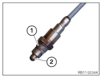
- Prepare the oxygen sensor.
Do not damage the sensor ceramics.
- Thread
- Sensor ceramics
NOTE:
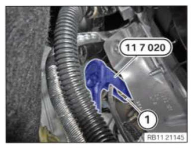
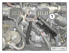
The cable of the Lambda oxygen sensor is black. The installation location of the Lambda oxygen sensor is in front of the catalytic converter.
- Screw in the Lambda oxygen sensor (1) and tighten with the special tool 0 491 074 (11 7 020).
TIGHTENING TORQUES SPECIFICATION
| Lambda control sensor | ||
|---|---|---|
| M18x1.5 | Tightening torque | 50 Nm |
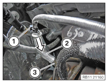
- Guide in heat protection (2) in direction of arrow and install.
- Make sure that the heat protection (2) is against the stop (3).
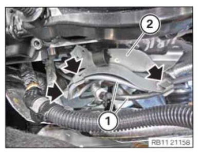
- Replace the cable ties (1).
Parts: Cable tie
- Guide in cable tie (1) and install.
- Feed in bracket (2) of positive battery cable and position.
- Fasten cable (1) in clamps (arrows).
- Version A (without mild hybrid technology): CAUTION: Improper routing of the positive battery cable.
Risk of short circuits!- Route the positive battery cable without abrasions and do not trap.
- Feed in bracket (5) of positive battery cable and position.
- Tighten screws (arrows).
TIGHTENING TORQUES SPECIFICATION
| Holder, positive battery cable to cylinder head cover | ||
|---|---|---|
| 6x18 | Tightening torque | 6 Nm |
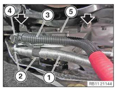
- Secure the positive battery cable (1) at the clamps (2).
- Secure the positive battery cable (3) at the clamps (4).
- Version B (with mild hybrid technology): CAUTION: Improper routing of the positive battery cable.
Risk of short circuits!- Route the positive battery cable without abrasions and do not trap.
- Feed in bracket (3) of positive battery cable and position.
- Tighten screws (arrows).
TIGHTENING TORQUES SPECIFICATION
| Holder, positive battery cable to cylinder head cover | ||
|---|---|---|
| 6x18 | Tightening torque | 6 Nm |
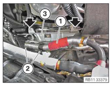
- Secure the positive battery cable (1) at the clamps (2).
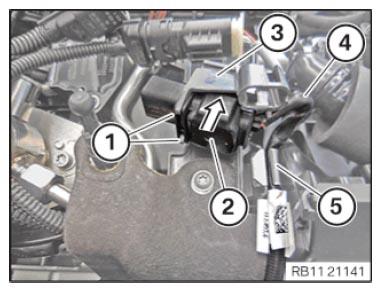
- Guide in connector (2) to carrier plate (3) in the arrow direction and connect it.
- Locks (1) must engage audibly.
- Secure cable (4) to the clamp (5).
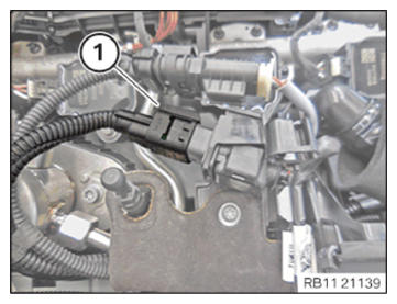
- Connect connectors (1) and lock.
The connector (1) must engage audibly.
- Connect and lock connector (1).
- Guide connector (1) into the carrier plate and connect it.
Connector (1) must engage audibly.
Follow-up work
- Refer to INSTALLING ACOUSTIC COVER AT REAR .
- Refer to INSTALLING ACOUSTIC COVER .
- Refer to INSTALLING THE FRONT HOOD SEAL AT THE REAR .