Remounting Frontal Light Electronics Right (FLER)
NOTE:
RISK OF DAMAGE Electrostatic discharge. Damage to or destruction of electrical components.
- Leave electrical components in original packaging until just before they are installed. Use the original packaging only for any return shipments. Always package removed components straight away.
- Read and comply with user information on using the associated special tool 12 7 060.
- Only touch the housings of electrical components. Do not touch pins or multi-pin connectors directly.
- Wear electrically conductive clothing and antistatic shoes (with ESD symbol).
- For additional information see: 61 35... NOTES for ESD protection (electrostatic discharge)
NOTE:
TECHNICAL INFORMATION
Notes on headlight adjustment are a fundamental requirement for these repair instructions and must be complied with at all times.
For additional information see: 63 10... Test PREREQUISITE for adjusting headlights
Notes on headlight adjustment are a fundamental requirement for these repair instructions and must be complied with at all times.
For additional information see: 63 10... Test PREREQUISITE for adjusting headlights
Remove the right-hand frontal light electronics (FLER)
NOTE:
Description is for left component only. Procedure on the right side is identical.
Install the Frontal Light Electronics
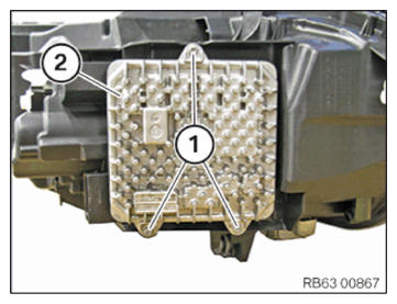
- Loosen screws (1).
- Pull Frontal Light Electronics (2) out of the headlight.
- Unlock and disconnect connector (1).
- Remove the Frontal Light Electronics (2).
Installing the right front light electronics (FLER)
NOTE: Description is for left component only. Procedure on the right side is identical.Install the Frontal Light Electronics
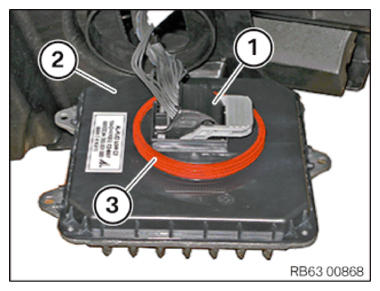
- Check seal (3) on Frontal Light Electronics (2) for damage and replace it if necessary.
- Connect connector (1).
Check
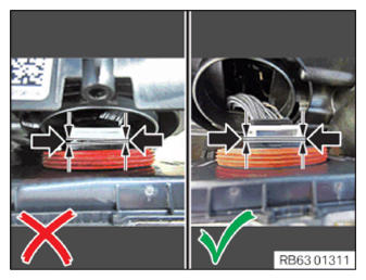
- After locking:
check the tight fit of the plug connection.
Result
» The tight fit is not correct.
Measure
- Release the connector and check the lock for mechanical damage.
Measure
- Replace any damaged connector components.
Measure
- Position the connector at a right angle to the direction of insertion, push in and lock.
Measure
- Check again for a tight fit.
- Position the frontal light electronics (2) in the headlight.
- Tighten the screws (1).TIGHTENING TORQUES SPECIFICATION
Frontal light electronics (FLE) PT-SCREW 40x12 Tightening torque 1.5 Nm
Follow-up Work
- When replacing laser headlights: PROGRAMING/ENCODING the integrated laser control unit
- Adjust HEADLIGHTS .