Pinning the connector again
- Step 1)
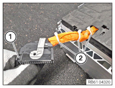
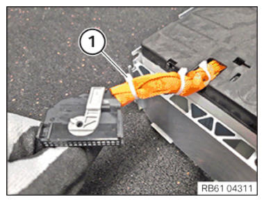
- Carefully bend up the snap-in lug (1) and pull out the pin strip.
- Carefully open the cable tie (2) and remove the line protection.
- Check that no lines have been damaged by removing the cable ties (2).
- Step 2)
- Observe the following repair procedures:
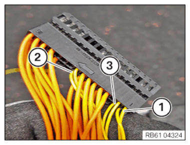
Unpin the lines (1), (2), (3) from the positions (example image).
The lines (1), (2), (3) must not be interchanged and must be pinned in the original position again. Overviews of NTC sensors (1), (2), (3) are shown in image RB6104322.
Recommendation: Replace the lines one at a time.
Pin assignment for SP03, SP05, SP09
Pin position in the connector Position in the image Signal 1 1 - 2 3 NTC1 + 9 2 NTC9+ 17 1 - 18 3 NTC1 + 25 2 NTC9+ - Steps 3 to 5 show the replacement of the pins of the individual line.
- This process is to be used for all 6 lines.
- Step 3
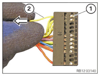
- Press in place (1) with a suitable non-metallic tool.
- Unpin the line (2) in arrow direction.
- Step 4
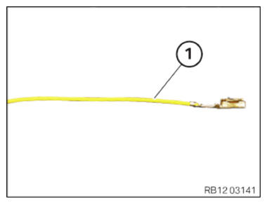
- Determining the length of the new
line (1) from the repair kit:
Length of removed line + 1 cm.
- Cut the new line (1) from the repair kit to the determined length.
- Strip off insulation of the new line (1).
- Crimp the new line (1) with pin (pin 6 905 964).
- Step 5
- Install pin for new line (1) (see step 9 .
- Repeat this step with all lines.
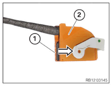
- Slide the pin strip (1) in arrow direction into the connector (2).
- Provide the lines with cable protection and attach cable ties (1).
- The cell module can be installed and the standby state of the vehicle is established. Before the following step and delivery to the customer, the vehicle cannot be moved for 24 h so that the adhesive reaches its final strength.
Follow-up work
- CHECK the temperature.