Installing coolant expansion tank
Further information is available.
Check
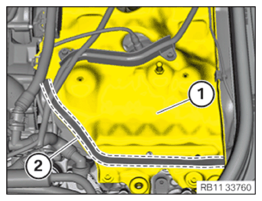
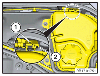
- Check if the foam seal on retaining bridge (1) in area (2) is damaged, porous, loose or present.
Result
» Foam seal (2) is damaged or porous or loose.
Measure
- Replace the foam seal (2).
Parts: foam
Measure
- Clean any foam seal residue or adhesive residue on the bonding surface in area (2) with cleaning agent R2.
Parts: Cleaning agent
Measure
- Bond foam seal (2).
Result
» Foam seal (2) is not installed.
Measure
- Retrofit foam seal (2).
Parts: foam
Measure
- Clean the bonding surface in area (2) with cleaning agent R2.
Parts: Cleaning agent
Measure
- Bond the foam with an adhesive.
NOTE:
RISK OF DAMAGE
Injectors contaminated with coolant.
Damage to and failure of injectors that were coated with coolant for an extended period.
Injectors contaminated with coolant.
Damage to and failure of injectors that were coated with coolant for an extended period.
- Covering injectors with suitable auxiliary materials before testing or topping up the coolant is mandatory.
- Covering injectors with suitable auxiliary materials before working on the cooling system in the area of the injectors is mandatory.
- If necessary, draw off all of the coolant from the coolant expansion tank.
- Always clean injectors or injector shafts contaminated with coolant (e.g. with compressed air).
CAUTION:
Swirling dirt particles caused by compressed air.
Injury hazard!
Injury hazard!
- Collect dirt particles, e.g. when blowing out, use cloth to do so.
- Wear safety goggles.
CAUTION:
Materials harmful to health.
Contact with fluids harmful to health!
Contact with fluids harmful to health!
- Note and follow safety instructions on containers.
- Conduct all work in appropriate personal protective equipment only.
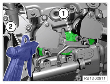
- Check the injector shafts for coolant residues (1).
- If there are coolant residues (1) in the injector shaft: Clean the injector shafts with an air gun (2).NOTE: Schematic diagram is for example purposes. Some parts may differ in certain details.
- Illustrated on the S63T4:
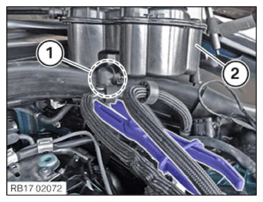
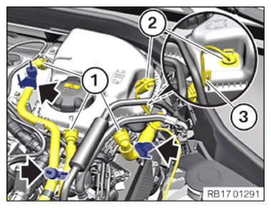
- Position the coolant expansion tank (2).
- Connect and lock coolant hose in area (1).NOTE: Schematic diagram is for example purposes. Some parts may differ in certain details.
- Illustrated on the S63T4:
- Remove the seal plug (1).
- Secure clamps (3).
- Connect connectors (2) and lock.
The connector (2) must engage audibly.
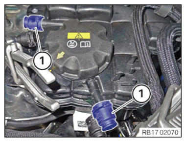
- Connect and lock the coolant lines (1).
Coolant lines (1) must engage audibly.
- Remove the standard disconnection tool (arrows).NOTE: Schematic diagram is for example purposes. Some parts may differ in certain details.
- Illustrated on the S63T4:
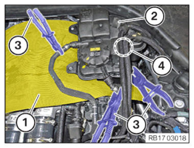
- Position the coolant expansion tank (2).
- Clip the fuel lines in area (4) into expansion tank (2).
- Remove clamping pliers (3).
- Remove the rubber mat (1).
- Connect the holder (4) and lock.
The holder (4) must engage audibly.
- Secure the coolant hose (3) on the coolant expansion tank (2).
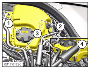
- Check the rubber mount (1) for correct fit.
- Equipment specification with gasoline particulate filter:
Guide the holder of gasoline particulate filter (2) downwards into the guide.
Tighten down screw (1).
TIGHTENING TORQUES SPECIFICATIONGasoline particulate sensor to coolant expansion tank M6x20 screw Tightening torque 8 Nm - Equipment specification with gasoline particulate filter:
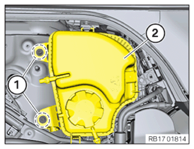
- Position the coolant expansion tank (2).
- Tighten the screws (1).TIGHTENING TORQUES SPECIFICATION
Coolant reservoir M6x20 screw Tightening torque 11 Nm - Equipment specification with gasoline particulate filter:
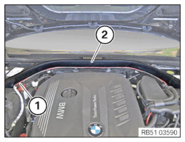
Press the rear hood seal (2) into the guide.
- Guide cable (1) into the holders.
- Check if the rear hood seal (2) and cable (1) fit correctly.
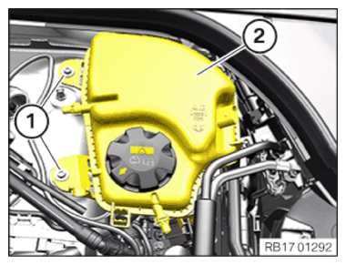
- Feed in and install coolant expansion tank (2).
Tighten down screws (1).
TIGHTENING TORQUES SPECIFICATIONCoolant reservoir M6x20 screw Tightening torque 11 Nm NOTE: TECHNICAL INFORMATION
Follow notes for repair work on the cooling system.
For additional information see:
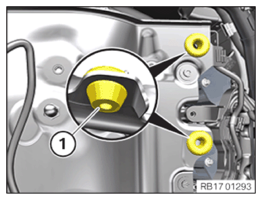
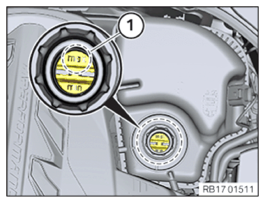
17 00... INSTRUCTIONS FOR REPAIR WORK ON COOLING SYSTEM - Top up the coolant expansion tank (1) with coolant up to the maximum mark (2).
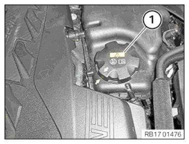
- Close the sealing cap (1) until the arrows
align.
Follow-up work
- Refer to INSTALLING THE CONTROL UNIT BRACKET FOR CYLINDERS 5 TO 8 .
- Refer to INSTALL CLEAN AIR PIPE, TOP .
- Refer to INSTALLING THE COVER OF THE LEFT DME CONTROL UNIT .
- Refer to DISCONNECTING ALL BATTERY GROUND LEADS .