Replacing the coolant lines for the exhaust turbocharger
WARNING:
Hot fluids.
Risk of scalding!
Risk of scalding!
- Conduct all work in the vehicle wearing appropriate personal protective equipment only.
CAUTION:
Materials harmful to health.
Contact with fluids harmful to health!
Contact with fluids harmful to health!
- Note and follow safety instructions on containers.
- Conduct all work in appropriate personal protective equipment only.
NOTE:
TECHNICAL INFORMATION
Collect and dispose of emerging fluids. Observe country-specific waste disposal regulations.
Collect and dispose of emerging fluids. Observe country-specific waste disposal regulations.
NOTE:
TECHNICAL INFORMATION
Follow notes for repair work on the cooling system.
For additional information see:
INSTRUCTIONS FOR REPAIR WORK ON COOLING SYSTEM
Follow notes for repair work on the cooling system.
For additional information see:
INSTRUCTIONS FOR REPAIR WORK ON COOLING SYSTEM
NOTE:
TECHNICAL INFORMATION
Immobilization period-long fill of coolant!
Do not reuse used coolant.
When replacing and removing components which rely on the corrosion protection effect of the coolant, it is essential to change the coolant. The cooling system must therefore be emptied and refilled.
In the case of other removal work involving the draining of part quantities of coolant, the coolant level must be topped up with new coolant.
NOTE:
TECHNICAL INFORMATION
Filling without the vacuum filling equipment (watering can filling) is not permitted .
If this is not observed, there is a risk of component damage or engine damage.
The filling specification must be observed.
It is essential to visually check the vacuum filling equipment before use to check that it is functioning correctly and clean.
It is not permissible to operate the vehicle if the filling procedure has not been fully completed. Otherwise there may be functional limitations (degradation) or overheating.
A bleeding procedure is required after a part has been exchanged in the cooling system and/or after refilling the cooling system.
Preliminary work
- Refer to DISCONNECTING ALL BATTERY GROUND LEADS .
- Refer to REMOVING THE FRONT UNDERBODY PROTECTION OR FRONT THRUST FIELD .
- Refer to REMOVING THE UNDERBODY PROTECTION OF THE STEERING GEAR AND THRUST FIELD RESPECTIVELY .
- Refer to REMOVING THE COVER ON LEFT AND RIGHT IN THE ENGINE COMPARTMENT AT THE TOP .
- Refer to REMOVING FRONT CROSS CONNECTION .
- Refer to REMOVING THE REAR TOP CROSS CONNECTION .
- Refer to REMOVING FAN COWL .
- Refer to DRAINING COOLANT .
- Refer to REMOVING THE ACOUSTIC COVER .
- Refer to REMOVING INTAKE SILENCER HOUSING .
- Refer to REMOVING THE LAMBDA OXYGEN SENSOR AND THE MONITORING OXYGEN SENSOR FOR CYLINDERS 1 TO 4 .
- Refer to REMOVING THE LAMBDA OXYGEN SENSOR AND THE MONITORING OXYGEN SENSOR FOR CYLINDERS 5 TO 8 .
- Refer to REMOVING ENGINE VENTILATION LINE .
- Refer to REMOVING UPPER HEAT SHIELD .
- Refer to REMOVING RIGHT CHARGE AIR LINE .
- Refer to REMOVING THE LEFT CHARGE AIR LINE .
- Refer to REMOVING RIGHT CLEAN AIR PIPE .
- Refer to REMOVING LEFT CLEAN AIR PIPE .
- Refer to REMOVING THE IGNITION COILS ON CYLINDER 5 .
- Refer to PARTIALLY DISENGAGE THE FUEL SUPPLY LINE .
- Refer to REMOVING THE BRACKET OF THE OXYGEN SENSOR CONNECTOR .
- Refer to RELEASING THE OIL FEED LINE FROM THE EXHAUST TURBOCHARGER OF CYLINDERS 5 TO 8 .
- Refer to RELEASING THE OIL FEED LINE FROM THE EXHAUST TURBOCHARGER OF CYLINDERS 5 TO 8 .
- Refer to RELEASING THE OIL FEED LINE FROM THE EXHAUST TURBOCHARGER OF THE CYLINDERS 1 TO 4 .
- Refer to LOOSEN OIL FEED LINE ON EXHAUST TURBOCHARGER OF CYLINDERS 1 TO 4 .
WARNING:
Hot exhaust system.
Risk of burning!
Risk of burning!
- Any work must exclusively be carried out with an exhaust system that has cooled down.
WARNING:
Hot fluids.
Risk of scalding!
Risk of scalding!
- Conduct all work in the vehicle wearing appropriate personal protective equipment only.
WARNING:
Hot surfaces.
Risk of burning!
Risk of burning!
- Perform all work only on components that have cooled down.
Differentiation of production versions
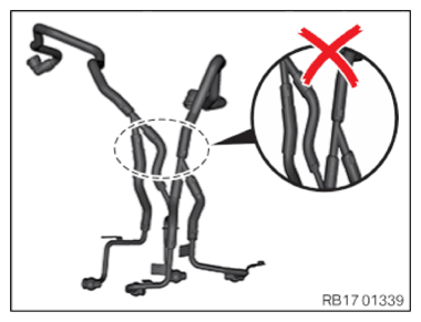
- Coolant lines with Y-shaped connectors may no longer be installed.
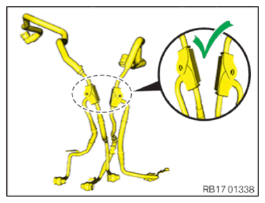
- Only coolant lines with a distributor block may be installed.
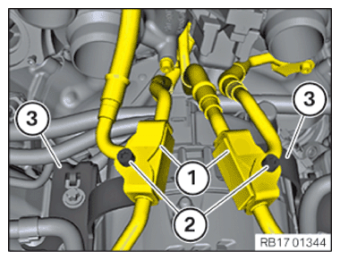
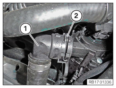
For equipment specification with Y-shaped connectors
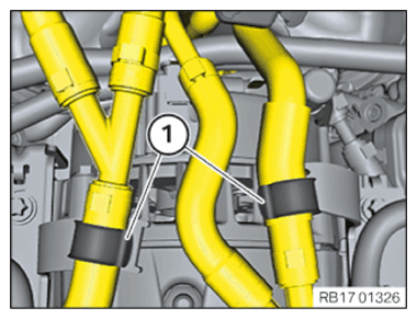
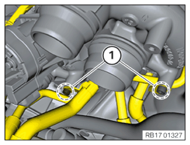
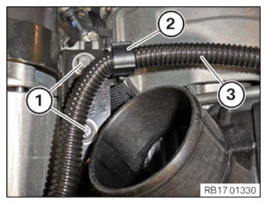
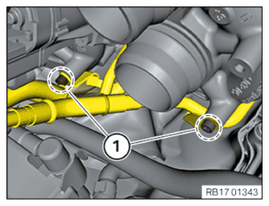
- Unclip the coolant lines from the holders (1).
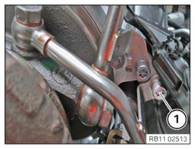
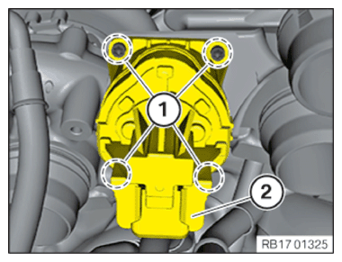
- Loosen screws (1).
- Loosen screws (1).
- Loosen screws (1).
- Loosen screws (1).
- Remove the screws (1) with the sealing rings.
- Feed out the coolant lines forwards.
- Unlock the wiring harness mounting (2).
- Set wiring harness (3) aside.
NOTE:
TECHNICAL INFORMATION
The sequence of the steps must be observed and followed.
The sequence of the steps must be observed and followed.
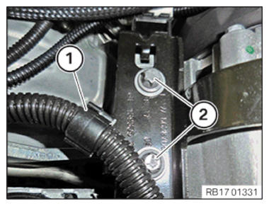
- Loosen screws (1).
Only one side of the attachment may be released from the alternator!
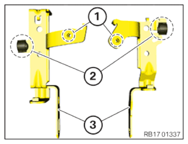
- Remove the bracket of the coolant hoses.
- Position the bracket of the affected side (3) from the retrofit kit.
- Remount the affected wiring harness mounting (2).
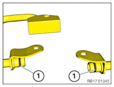
- Only brackets with the holes (1) may be installed.
NOTE:
TECHNICAL INFORMATION
The sequence of the steps must be observed and followed.
The sequence of the steps must be observed and followed.
- Tighten the screws (1).
TIGHTENING TORQUES SPECIFICATION
| Alternator to cylinder head | ||
|---|---|---|
| M8x85 | tightening torque | 22 Nm |
- Position wiring harness (3).
- Lock the wiring harness mounting (2).
- Unlock the wiring harness mounting (1).
- Place wiring harness to one side.
NOTE:
TECHNICAL INFORMATION
The sequence of the steps must be observed and followed.
The sequence of the steps must be observed and followed.
- Loosen screws (2).
Only one side of the attachment may be released from the alternator!
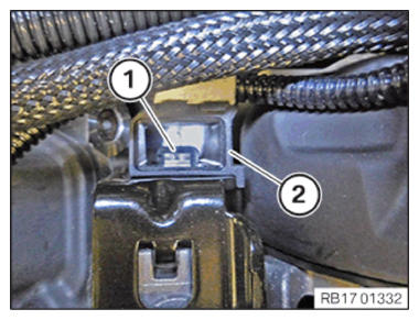
- Unlock the wiring harness mounting (2) on the retaining tab (1).
- Push the wiring harness mounting (2) upwards and set aside.
- Remove the bracket of the coolant hoses.
- Position the bracket of the affected side (3) from the retrofit kit.
- Remount the affected wiring harness mounting (2).
- Only brackets with the holes (1) may be installed.
NOTE:
TECHNICAL INFORMATION
The sequence of the steps must be observed and followed.
The sequence of the steps must be observed and followed.
- Tighten screws (2).
TIGHTENING TORQUES SPECIFICATION
| Alternator to cylinder head | ||
|---|---|---|
| M8x85 | tightening torque | 22 Nm |
- Position wiring harness.
- Lock the wiring harness mounting (1).
- Position wiring harness mounting (2).
- Slide the wiring harness mounting (2) down.
The wiring harness mounting (2)must audibly (1)lock on the retaining tab.
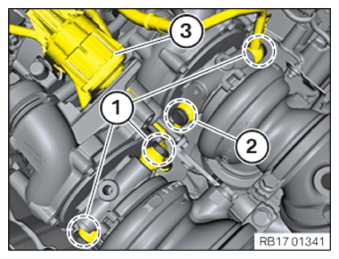
For equipment specification with distributor block
- Loosen screws (2).
- Release the distributor blocks from the brackets (3).
- Disconnect coolant lines (1).
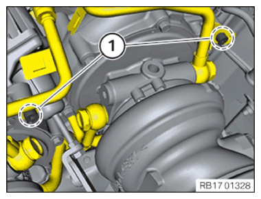
- Loosen screws (1).
- Loosen screws (1).
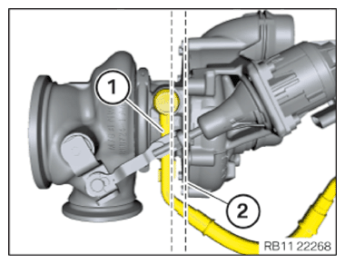
- Loosen screw (1).
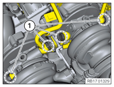
- Loosen screws (1).
- Carefully pull the wastegate valve controller (3) towards the front.
The linkage on the wastegate valve controller must be subjected to any side load.
- Loosen screw (2).
- Remove the screws (1) and screw (2) with the sealing rings.
- Feed out the coolant lines forwards.
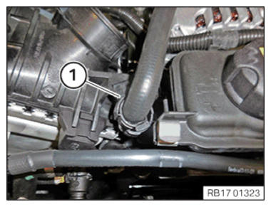
- Release the tank vent line from the holders (1).
- Release the holding clip (1).
- Loosen screws (1).
- Release the vehicle wiring harness from the fixtures in area (2).
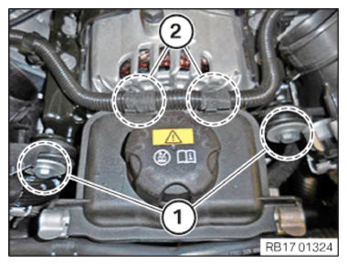
- Release the holding clip (2).
- Unlock the retaining tabs (1).
- Carefully pull the coolant expansion tank (3) forward.
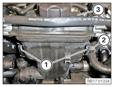
- Unlock the retaining clip (2).
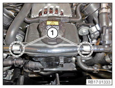
- Disconnect the coolant hose (1) from the thermostat housing.
- Feed out the coolant hose (1).
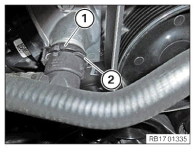
- Unlock the retaining clip (2).
- Disconnect the coolant hose (1) from the electric coolant pump.
- Feed out the coolant hose (1).
- Coolant lines with Y-shaped connectors may no longer be installed.
- If applicable, remount the mounting clips.
- Only coolant lines with a distributor block may be installed.
- Insert the coolant lines and position.
Mind the changed line routing.
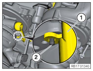
- For equipment specification with centering pin.
- The return line of cylinder bank 2 (1) must be fastened on the centering pin (2).
Mind the changed locating point.
- For equipment specification without centering pin.
- The return line of cylinder bank 2 (1) must be screwed parallel to the edge on the compressor housing (2).
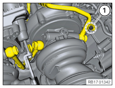
- Use new banjo bolts with sealing rings from the retrofit kit.
Parts : Banjo bolts
Parts : Sealing rings
- Position and tighten the banjo bolts (1).
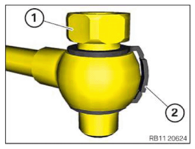
TIGHTENING TORQUES SPECIFICATION
| Banjo bolt for coolant line on exhaust turbocharger | ||
|---|---|---|
| Banjo bolt M14x1.5 Replace screw. Replace sealing rings. |
tightening torque | 35 Nm |
- Carefully pull the wastegate valve controller (3) towards the front.
The linkage on the wastegate valve controller must be subjected to any side load.
- Position and tighten the banjo bolt (2).
TIGHTENING TORQUES SPECIFICATION
| Banjo bolt for coolant line on exhaust turbocharger | ||
|---|---|---|
| Banjo bolt M14x1.5 Replace screw. Replace sealing rings. |
tightening torque | 35 Nm |
- Position the wastegate valve controller (3).
- Position and tighten the screw (1).
TIGHTENING TORQUES SPECIFICATION
| Coolant line to exhaust turbocharger | ||
|---|---|---|
| M6x16 screw | Tightening torque | 10 Nm |
- Position and tighten the bolts (1).
TIGHTENING TORQUES SPECIFICATION
| Coolant line to exhaust turbocharger | ||
|---|---|---|
| M6x16 screw | Tightening torque | 10 Nm |
- Position the wastegate valve controller (2).
- Tighten down screws (1).
TIGHTENING TORQUES SPECIFICATION
| Wastegate valve controller to exhaust turbocharger | ||
|---|---|---|
| M4x12 | tightening torque | 2 ± 0.3 Nm |
- Feed in the coolant hose (1).
- Connect the coolant hose (1) to the electric coolant pump.
- The retaining clip (2) must lock audibly.
- Feed in the coolant hose (1).
- Connect the coolant hose (1) to the thermostat housing.
- The retaining clip (2) must lock audibly.
- Carefully slide the coolant expansion tank (3) to the rear.
- The retaining tabs (1) must engage audibly.
- Fasten the holding clip (2).
- Fasten the vehicle wiring harness on the attachments in area (2).
- Tighten down screws (1).
TIGHTENING TORQUES SPECIFICATION
| Charge air cooler to engine | ||
|---|---|---|
| M6x35 screw | Tightening torque | 8 Nm |
- Fasten the holding clip (1).
- Fasten the tank vent line in the brackets (1).
- Coat the O-rings (1) with coolant.
- Connect coolant lines (1).
- Position the distributor blocks on the brackets (3).
- Position the screws (2).
- Tighten the distributor blocks on the brackets (2) with the screws (3).
TIGHTENING TORQUES SPECIFICATION
| Distributor block to holder | ||
|---|---|---|
| M6x30 screw | Tightening torque | 8 Nm |
Follow-up work
- Refer to ATTACHING THE OIL SUPPLY LINE ON THE EXHAUST TURBOCHARGER OF CYLINDERS 1 TO 4 .
- Tighten down screw (1).TIGHTENING TORQUES SPECIFICATION
Oil feed line to exhaust turbocharger M6x16 Tightening torque 10 Nm - Refer to SECURING OIL FEED LINE ON EXHAUST TURBOCHARGER OF CYLINDERS 5 TO 8 .
- Refer to SECURING OIL FEED LINE ON EXHAUST TURBOCHARGER OF CYLINDERS 5 TO 8 .
- Refer to INSTALLING THE BRACKET FOR THE OXYGEN SENSOR CONNECTOR .
- Refer to INSTALLING FUEL SUPPLY LINE (PARTIAL INSTALLATION) .
- Refer to INSTALLING THE IGNITION COILS ON THE 5TH CYLINDER .
- Refer to PREPARING FOR THE INSTALLATION OF THE CLEAN AIR PIPE .
- Refer to INSTALLING LEFT CLEAN AIR PIPE .
- Refer to INSTALLING RIGHT CLEAN AIR PIPE .
- Refer to INSTALLING THE LEFT CHARGE AIR LINE .
- Refer to INSTALLING THE RIGHT CHARGE AIR LINE .
- Refer to INSTALLING HEAT SHIELD, TOP .
- Refer to INSTALLING ENGINE VENTILATION LINE .
- Refer to INSTALLING THE LAMBDA OXYGEN SENSOR AND THE MONITORING OXYGEN SENSOR FOR CYLINDERS 5 TO 8 .
- Refer to INSTALLING THE LAMBDA OXYGEN SENSOR AND THE MONITORING OXYGEN SENSOR FOR CYLINDERS 1 TO 4 .
- Refer to INSTALLING INTAKE FILTER HOUSING .
- Refer to INSTALLING ACOUSTIC COVER .
- Refer to CONNECTING THE COOLANT HOSE TO THE RADIATOR .
- Refer to INSTALLING FAN COWL .
- Refer to INSTALLING THE REAR TOP CROSS CONNECTION .
- Refer to INSTALLING FRONT CROSS CONNECTION .
- Refer to INSTALLING THE COVER ON THE LEFT AND RIGHT IN THE ENGINE COMPARTMENT AT THE TOP .
- Refer to INSTALLING THE UNDERBODY PROTECTION OF THE STEERING GEAR OR THE FRONT THRUST FIELD .
- Refer to INSTALLING THE FRONT UNDERBODY PROTECTION OR FRONT THRUST FIELD .
- Refer to DISCONNECTING ALL BATTERY GROUND LEADS .
- Refer to FILLING AND VENTING THE COOLANT CIRCUIT .