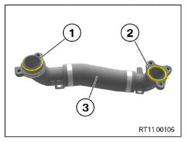
Install coolant line between the coolant pump and cylinder head
- Check the sealing ring (1) and (2) for damage and replace the coolant line (3) if necessary.
Parts: Sealing rings
NOTE:
TECHNICAL INFORMATION
When assembling, it is essential to observe screwing sequences and tightening torques.
Failure to comply with the regulations can lead to leaks and damage.
When assembling, it is essential to observe screwing sequences and tightening torques.
Failure to comply with the regulations can lead to leaks and damage.
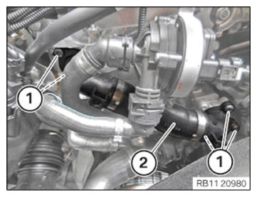
- Feed in and install coolant line (2).
- Hand-tighten the bolts (1).
- Tighten down screws (1).TIGHTENING TORQUES SPECIFICATION
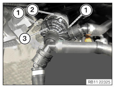
Coolant line to coolant pump/cylinder head M6x20 Tightening torque 8 Nm - Feed in and position the electric coolant pump (3).
- Insert and install the retainer (2).
- Make sure the retainer (2) is positioned correctly.NOTE: RISK OF DAMAGE
Improper screw length can cause component damage.
The use of screws of improper length can lead to component damage.- Note the correct screw length.
- Install screws that correspond to the original length.
- Tighten the screws (1).TIGHTENING TORQUES SPECIFICATION
Electric coolant pump on component carrier M6 Replace screws. tightening torque 8 Nm
Follow-up work
- Refer to INSTALLING THE THROTTLE BODY .
- Refer to INSTALLING THE DRIVE BELT FOR THE COOLANT PUMP .
- Refer to INSTALLING THE ACOUSTIC COVER FOR THE ENGINE AT THE FRONT .
- Refer to INSTALLING CHARGE AIR LINE .
- Refer to INSTALLING RESONATOR .
- Refer to DISCONNECTING ALL BATTERY GROUND LEADS .
- Refer to FILLING AND VENTING THE COOLANT CIRCUIT .
- Refer to INSTALLING ACOUSTIC COVER .
- Refer to INSTALLING THE UNDERBODY PROTECTION OF THE STEERING GEAR OR THE FRONT THRUST FIELD .
- Refer to INSTALLING THE REAR THRUST FIELD .
- Refer to INSTALLING THE FRONT UNDERBODY PROTECTION OR FRONT THRUST FIELD .