Completely removing the prop shaft (plug-in - rear flexible disc)
Preliminary work
- Remove rear UNDERBODY PROTECTION .
- Remove the transmission on the side UNDERBODY PLANKING
- Remove the connecting support from the TUNNEL .
- If installed: remove the right and left TORSION STRUT where required.
- Remove the HEAT SHIELDS
NOTE:
RISK OF DAMAGE
Damage to prop shaft during removal.
Non-observance of the removal guidelines for the prop shaft on the rear axle differential may cause severe damage.
Damage to prop shaft during removal.
Non-observance of the removal guidelines for the prop shaft on the rear axle differential may cause severe damage.
- Do not disassemble the three-hole flange, flexible disc and prop shaft. The three-hole flange to the rear axle differential is balanced with the flexible disc and prop shaft.
- Loosen the recessed nut against the direction of travel in clockwise direction. The prop shaft must be loosened on the recessed nut only and exclusively in the direction of rotation otherwise the anti-twist lock of the bi-hexagonal flange nut is damaged.
- In the event of a damaged anti-twist lock on the bi-hexagonal flange nut: Replace the rear axle differential.
NOTE:
TECHNICAL INFORMATION
Compliance with the following instructions is required to avoid a humming from the prop shaft after refitting the prop shaft.
Compliance with the following instructions is required to avoid a humming from the prop shaft after refitting the prop shaft.
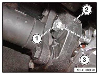
- The flexible disc screw connection (1) on the front at the prop shaft must
be marked in one plane with the flexible disc (2) and the three-bolt flange (3) before releasing.
- It is necessary to reassemble the three-hole flange (3) while installing, with the flexible disc (2) in the same position.
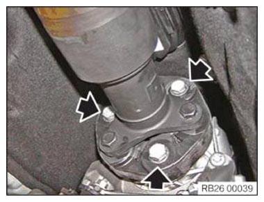
- Remove screws (arrows).
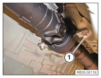
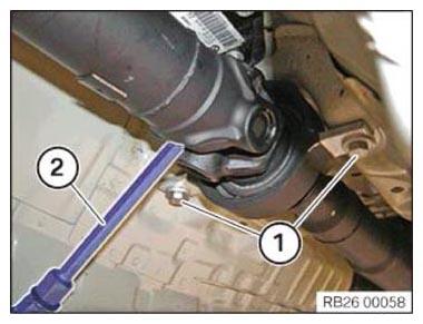
- Loosen screws (1).
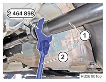
- Version with narrow universal joint:
Using special tool 2 464 898 and a suitable tool, (2) secure the prop shaft (1) at the middle universal joint so that it does not twist.
- Vehicles with wide universal joint:
Secure the juncture shaft on the center universal joint with a suitable tool (2) to protect it from twisting.
Remove screws (1) of the central mount only after opening the recessed nut fully.
NOTE: RISK OF DAMAGE
Damage to rear axle differential.
Non-observance of the removal and installation guidelines may cause severe damage to the rear axle differential.- Do not use the double hexagon head flange nut as counter support.
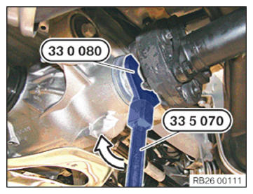
- Release the recessed nut using special tools 0 495 554 (33 5 070)
and 0 496 959 (33 0 080)
in the arrow direction (clockwise).
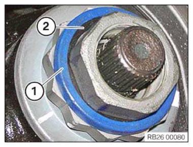
- Remove mounting clip (1) and seal (2).
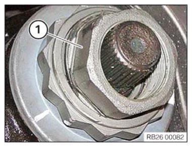
- Remove recessed nut (1).