Removing the engine from the lifting table
NOTE:
RISK OF DAMAGE
Engine damage due to missing motor oil.
Missing motor oil following repairs to the components in the oil circuit or replacement of the engine can lead to damage to the engine.
Engine damage due to missing motor oil.
Missing motor oil following repairs to the components in the oil circuit or replacement of the engine can lead to damage to the engine.
- Following repairs to components in the oil circuit or replacement of the engine, do not start the engine without observing the repair notes.
- It is imperative that you observe the repair notes following repairs to components in the oil circuit or replacement of the engine.
- For additional information, see the REPAIR NOTES .
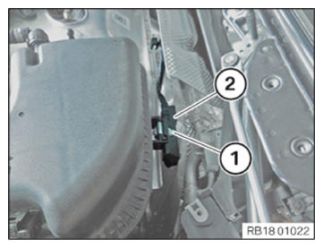
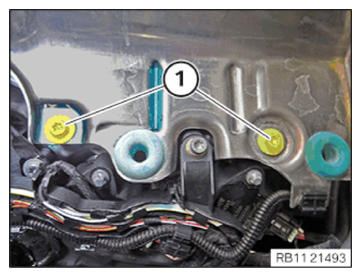
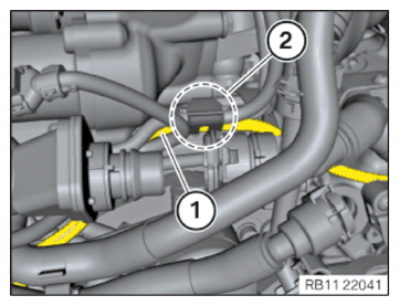
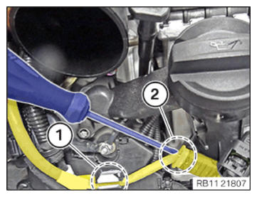
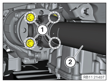
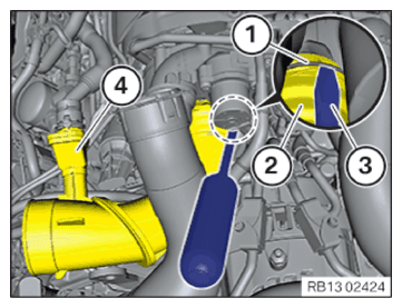
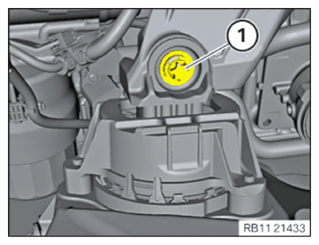
- Loosen screw (1).
- Remove the cover of the gasoline particulate filter sensor (2).
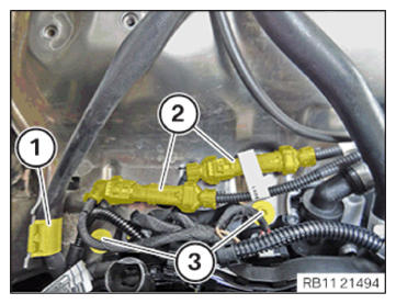
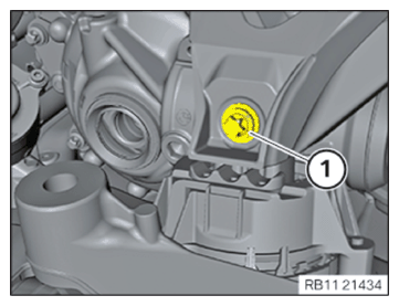
- Loosen screw (1).
- Remove the cover of the gasoline particulate filter sensor (2).
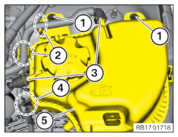
- Unlock and disconnect the coolant ventilation line (3).
- Unclip the coolant ventilation line in area (2) from the brackets.
- Unclip wiring harness mounting (4).
- Loosen screws (1).
- Thread out coolant expansion tank (5) and remove.
- Unclip the cable of the Lambda oxygen sensor from the bracket (1).
- Unlock and disconnect the engine ventilation line from the retaining clip in the region of (1).
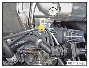
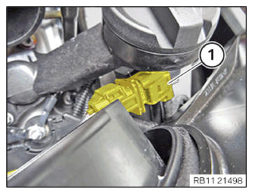
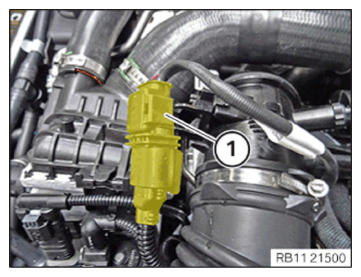
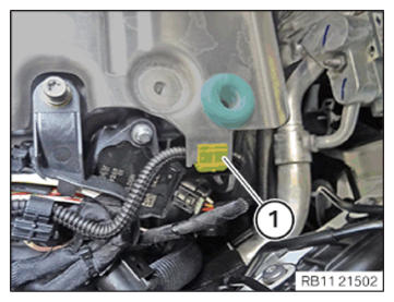
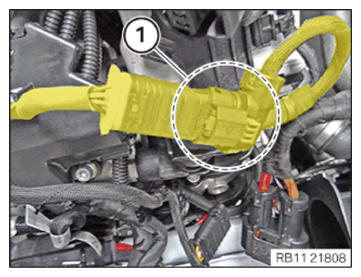
- Unlock plug connection (1) and disconnect.
- Feed out the right Lambda oxygen sensor and remove it.
- Release the left Lambda oxygen sensor (1) with the special tool 0 491 074 (11 7 020).
- Release the right Lambda oxygen sensor cable in area (1) from the cable bracket.
- Unclip the cable of the Lambda oxygen sensor from the bracket (1).
- Unlock plug connection (1) and disconnect.
- Unlock and disconnect the engine ventilation line from the retaining clip in the region of (1).
- Feed the connector (2) of the Lambda oxygen sensor through.
- Release the left Lambda oxygen sensor (1) with the special tool 0 491 074 (11 7 020).
- Release the left Lambda oxygen sensor cable in area (2) from the cable bracket.
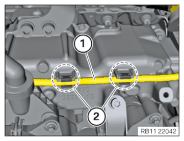
- Working upwards, unclip the engine ventilation line (1).
- Unclip the wiring harness from the attachments (2).
- Loosen screws (1).
- Unclip the transmission wiring harness from the bracket (1).
- Unclip the plug connection (2) from the heat shield upwards.
- Loosen screws (3).
- Unclip the wiring harness mounting (1) at the heat shield.
- Unclip the wiring harness mounting (1) at the heat shield.
- Lift out heat shield.
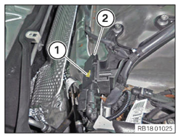
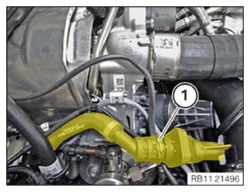
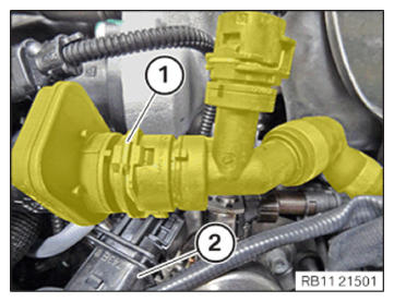
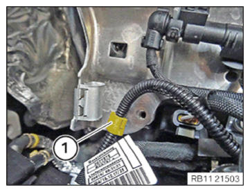
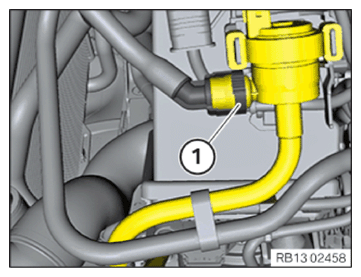
- Unlock and disconnect the quick-release coupling (1).
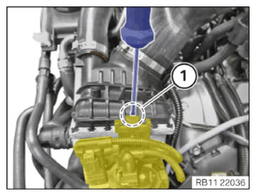
- Unlock the bracket in area (1) with a suitable screwdriver.
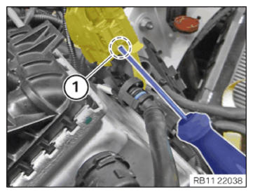
- Unlock the detent of the plug connection in area (1) with a suitable screw driver.
- Push the plug connection forwards.
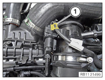
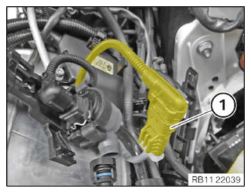
- Unlock plug connection (1) and disconnect.
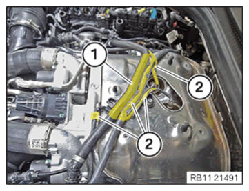
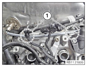
- Unclip the cable (1) of the oxygen sensor monitor from the holders (2).
- Unclip the cable (1) of the oxygen sensor monitor from the holders (2).
- Unclip the cable (1) of the oxygen sensor monitor from the holders (2).
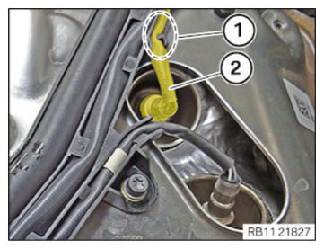
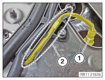
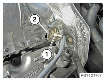
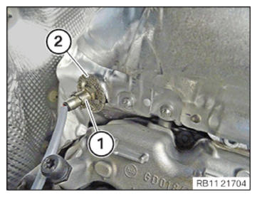
- Release retaining clip (1).
- Wipe off the heat protection wire ring (2) over the oxygen sensor monitor.
- Release and remove the oxygen sensor monitor with the special tool 0 491 074 (11 7 020).
- Unlock the detent of the plug connection in area (2) with a suitable screw driver.
- Push the plug connection forwards.
- Unclip cable of oxygen sensor monitor probe from the clamp (1).
- Unlock plug connection (1) and disconnect.
- Unclip cable of the oxygen sensor monitor probe from the clamps (1).
- Release retaining clip (1).
- Pull the heat protection wire ring (2) off over the oxygen sensor monitor.
- Release oxygen sensor monitor probe with the special tool 0 491 074 (11 7 020).
- Remove oxygen sensor monitor probe.
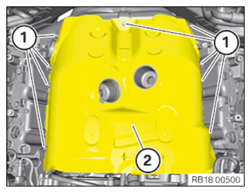
- Loosen screws (1).
- Remove upper heat shield (2).
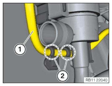
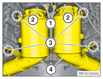
- Version with a gasoline particulate filter:
Release union nuts (2).
Unclip the pressure lines (3) from the retaining clips in the areas (1).
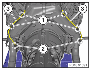
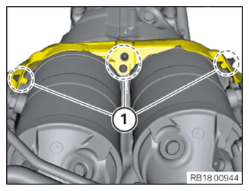
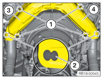
- Loosen screws (1).
- Loosen screws (1).
- Feed out the heat shield (3) and (4) at the retaining tabs (2).
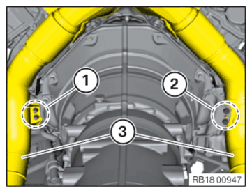
- Release the screws (1) at the V-ribbon clips (2).
- Release the screws in the area (3) at the catalytic converters (4).
- Loosen nuts (1).
- Loosen screws (2).
- Feed out and remove the catalytic converters (3).
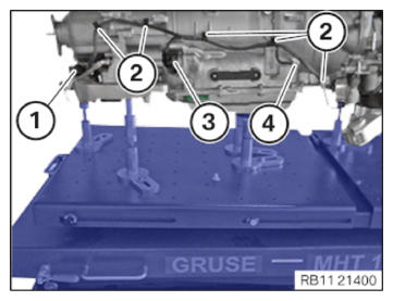
- Unlock and disconnect the plug connection (1) from the transfer box (TB).
- Release the wiring harness mountings (2).
- Unlock and disconnect the plug connection (3) from the automatic transmission.
- Release the screw in area (4).
- Remove ground cable.
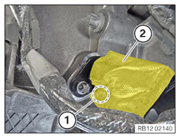
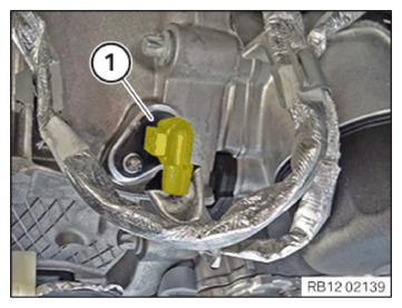
- Unlock the heat shield (2) on the push-button (1).
- Unlock plug connection (1) and disconnect.
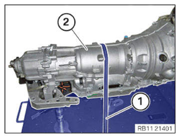
- Lash the transmission (2) with commercially available tensioning strap (1).
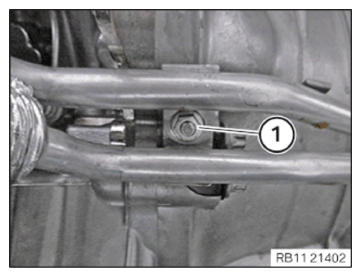
- Loosen nut (1).
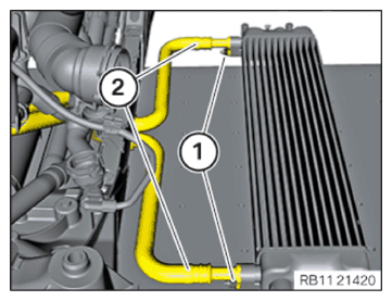
- Loosen screw (1).
- Release the hydraulic lines (2) from transmission oil cooler in the arrow direction.
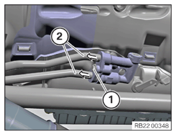
- Loosen screws (1).
- Lay the front prop shaft (2) downwards.
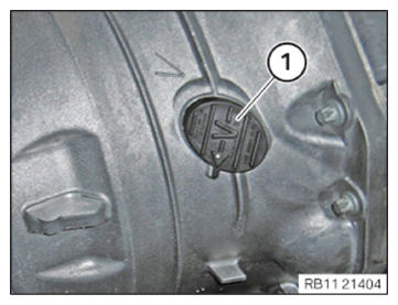
- Remove cover (1).
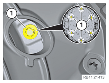
- Release converter bolt (1).
The crankshaft at central bolt may only be turned clockwise.
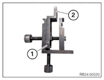
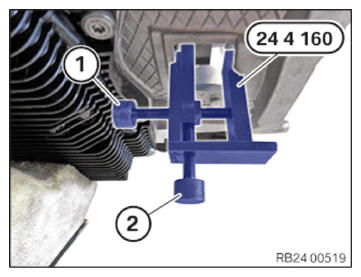
- Prepare the special tool 0 494 451 (24 4 160)
(1) with the special tool 0 494 622 (24 4 164)
(2) as shown.
- Insert special tool 0 494 451 (24 4 160) into the recess of the transmission housing and apply slight tension using the screw (1).
- Screw the bolt (2) in to the stop.
- Tighten down screw (1).
- Support engine.
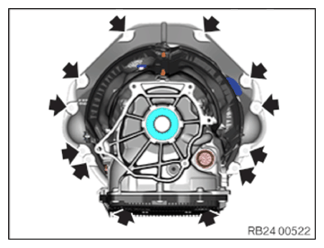
- Loosen the screws (arrows) and remove the transmission.
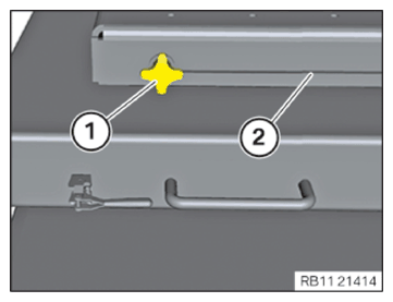
- Release the retaining screws (1) on both sides of the lifting table (2).NOTE: Check the plastic components of the locking mechanism or clamp for damage.
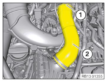
Replace the charge air ducts with damaged plastic components on the locking mechanism. - Unlock lock (1).
- Detach the right charge air line (2) from the exhaust turbocharger and set it aside.
- Using suitable screwdrivers (3), lever the retaining clips (1) upwards and unclip from the surrounding guides (2).
Retention of the retaining clip (2) in the unlocking position is not possible due to design reasons.
- Remove clean air pipe of bank 2 (4).
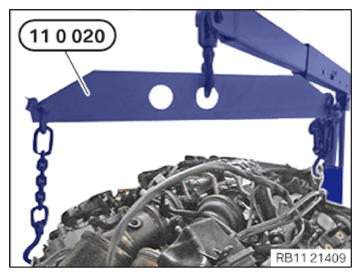
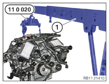
- Secure engine on engine mounting bracket with a workshop crane and special tool 0 490 567 (11 0 020).
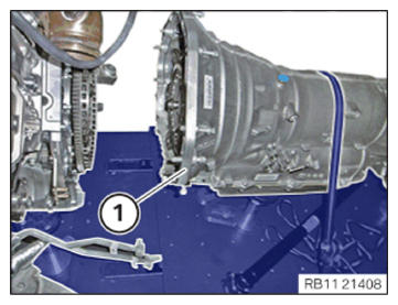
- Slide transmission (1) to the rear and disconnect from the engine.NOTE: Collect and dispose of emerging fluids. Observe country-specific waste disposal regulations.
- Variant with coolant radiator:
Release nuts (1).
Pull off the coolant lines (2).
- Loosen screw (1).
- Loosen screw (1).NOTE: The operations shown only for one side must be carried out on both sides.
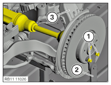
- Hand-tighten the screws (1).
- Release the central bolt of the output shaft.
- Remove the swivel bearing mount (2) and set it aside.
- Hold the swivel bearing (3) with the special tool 2 220 718. NOTE: The operations shown only for one side must be carried out on both sides.
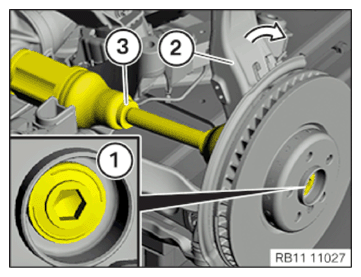
- Loosen screw (1).
- Tilt the swivel bearing (2) slightly forwards in the direction of the arrow.
- Loosen and remove the output shaft (3) at the front axle differential with a suitable tool.
- Lift engine with a workshop crane (1) and the special tool 0 490 567 (11 0 020) out of the engine mounts.