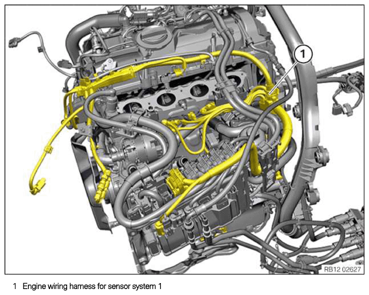
Installing the engine wiring harness for the sensor system 1
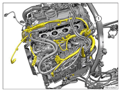
Engine wiring harness for sensor system 1
NOTE:
RISK OF DAMAGE
Improper routing of cables and wiring harnesses.
Trapped, crushed or damaged cables may cause short circuits and malfunctions.
Improper routing of cables and wiring harnesses.
Trapped, crushed or damaged cables may cause short circuits and malfunctions.
- Route all cables without abrasions, do not trap and crush.
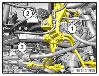
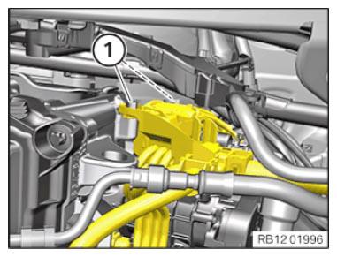
- Guide in and install the wiring harness section (1) for sensor system 1.
- Connect connectors (3) and lock.
The connector (3) must engage audibly.
- Tighten down screw (2).
TIGHTENING TORQUES SPECIFICATION
| Wiring harness section for engine to cylinder head cover | ||
|---|---|---|
| M6 | Tightening torque | 8 Nm |
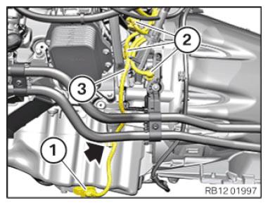
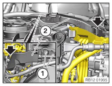
- Guide in the wiring harness section (1) and install.
- Guide in and install the wiring harness section (3) for sensor system 1.
- Connect connectors (2) and lock.
The connectors (2) must engage audibly.
- Secure clamps (arrow).
- Connect connectors (1) and lock.
The connector (1) must engage audibly.
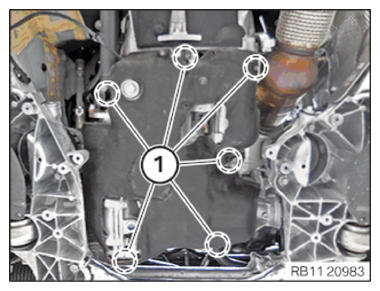
- Insert and install the acoustic cover of the oil sump.
- Guide in all expanding rivets (1) in the marked areas and install.
- Connect connectors (1) and lock.
- Make sure the connector (1) engages audibly.
- Secure clamps (2).
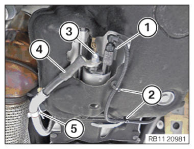
- Insert and install the positive battery cable (4).
- Secure positive battery cable (4) at the clamp (5).
- Tighten the nut (3) hand-tight.
CAUTION:
Improper routing of the positive battery cable.
Risk of short circuits!
Risk of short circuits!
- Route the positive battery cable without abrasions and do not trap.
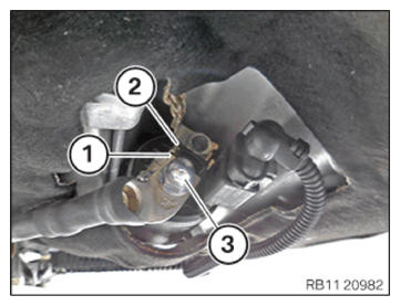
- Correctly attach the positive battery cable (1) to the anti-twist lock (2).
- Tighten the nut (3).
TIGHTENING TORQUES SPECIFICATION
| Battery positive lead to starter | ||
|---|---|---|
| M8 | Tightening torque | 13.5 Nm |
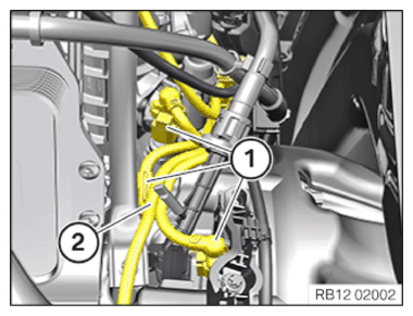
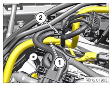
- Guide in and install the wiring harness section (2) for sensor system 1.
- Connect connectors (1) and lock.
The connectors (1) must engage audibly.
- Tighten down screws (1).
TIGHTENING TORQUES SPECIFICATION
| Cable bracket on rear cylinder head/transmission | ||
|---|---|---|
| M6 x 20 | Tightening torque | 8 Nm |
- Guide in the wiring harness section (2) and install.
- Make sure the detent (arrow) engages audibly.
- Tighten down screws (1).
TIGHTENING TORQUES SPECIFICATION
| Cable bracket on rear cylinder head/transmission | ||
|---|---|---|
| M6 x 20 | Tightening torque | 8 Nm |
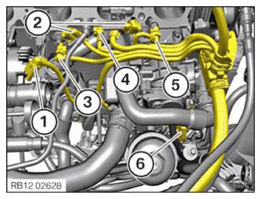
- Guide in and install the wiring harness section for sensor system 1.
- If fitted:
Attach connector (1) and lock it audibly.
- Attach connector (2) to the knock sensors and lock it audibly.
- Attach connector (3) to the changeover valve and lock it audibly.
- Attach connector (4) to the component temperature sensor and lock it audibly.
- Attach connector (5) to the temperature sensor and lock it audibly.
- Attach connector (6) to the heat management module and lock audibly.
- Guide in and install the wiring harness section (1) for sensor system 1 on the bracket (2).
Follow-up work
- Refer to INSTALLING INTAKE PLENUM .
- Refer to INSTALLING THE TANK VENT VALVE .
- Refer to INSTALLING CONTROL UNIT BRACKET .
- Refer to INSTALLING THE INTEGRATED POWER SUPPLY MODULE (PDM) .
- Refer to INSTALLING THE DME CONTROL UNIT .
- Refer to INSTALLING RESONATOR .
- Refer to CONNECTING NEGATIVE BATTERY CABLE .
- Refer to INSTALLING THE THERMOSTAT ON THE TRANSMISSION OIL LINES .
- Refer to FILLING AND VENTING THE LOW-TEMPERATURE COOLANT CIRCUIT .
- Refer to CHECKING/TOPPING UP THE OIL LEVEL IN THE AUTOMATIC TRANSMISSION .
- Refer to INSTALLING THE REAR THRUST FIELD .
- Refer to INSTALLING ACOUSTIC COVER AT REAR .
- Refer to INSTALLING ACOUSTIC COVER .
- Refer to INSTALLING THE FRONT HOOD SEAL AT THE REAR .
- Refer to INSTALLING THE UNDERBODY PROTECTION OF THE STEERING GEAR OR THE FRONT THRUST FIELD .
- Refer to INSTALLING THE FRONT UNDERBODY PROTECTION OR FRONT THRUST FIELD .
- Refer to TAKING HOOD OUT OF THE SERVICE POSITION .