Frame Reference Dimension REH-Hin-P-4100-G30 - V.1
General Information, Frame Reference Dimensions
The checkpoints shown serve to check the body and the set of attachments.
Dimensions in mm.
Dimension tolerances are:≤ 1000 mm ± 1.5 mm, ≥ 1000 mm ± 2.5 mm
The specified dimensions always refer to the center point of the bore or screw.
Measuring points on the right side of the vehicle are labeled with capital letters.
Measuring points on the left side of the vehicle are labeled with lowercase letters.
If only one measuring distance is specified, the measuring points on the left and right are symmetrical.
The views display 3-dimensional measurements.
3-Dimensional Measurements:
straight distance between 2 measuring points
Adjust both gauge tips of the beam compass 1 to the same height.
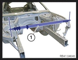
Measuring Tool:
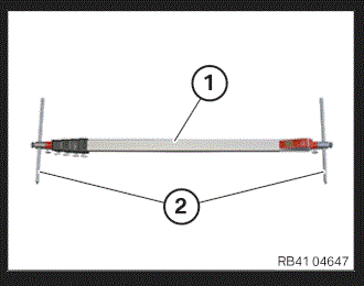
Carry out measurements using the beam compass 1.
If measurement with a beam compass is not possible, use a tape measure.
If tape measure is used, kinks and twisting should be avoided.
Adjust both gauge tips 2 of the beam compass 1 to the same height.
Frame Reference Dimensions For The Front End 3-Dimensional
Frame reference dimensions, front end
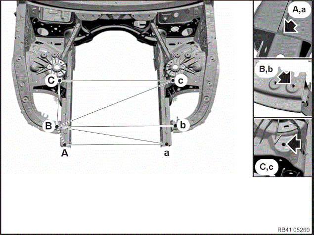
- Check the following frame reference dimensions on the vehicle:
A-a B-b A-B, a-b A-b, B-a C-c B-c, C-b C-C, b-c 854 932 261 930 898 983 360
Frame Reference Dimensions For The Floor Assembly Group (Part 1) 3-Dimensional
Frame reference dimensions of floor assembly group 1
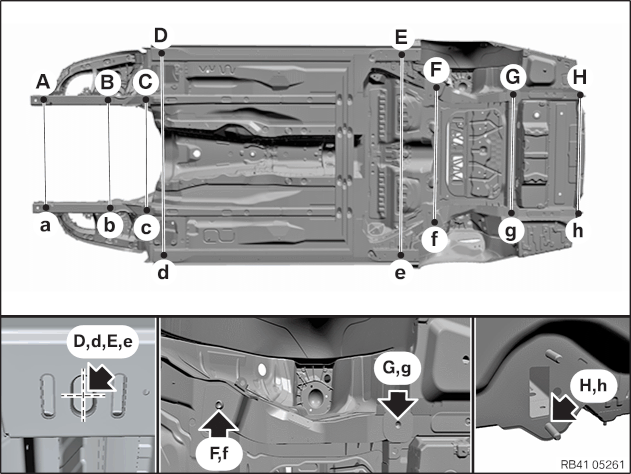
- Check the following frame reference dimensions on the vehicle:
A-a B-b C-c D-d, E-e F-f G-g H-h 858 858 858 1548 1070 950 942
Frame Reference Dimensions For The Floor Assembly Group (Part 2) 3-Dimensional
Frame reference dimensions of floor assembly group 2
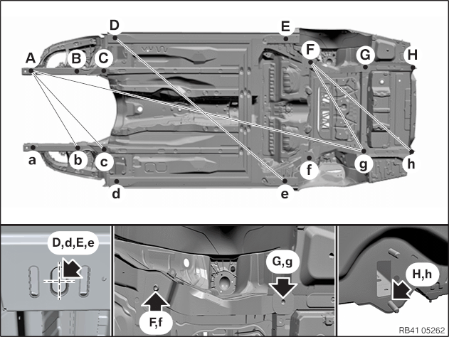
- Check the following frame reference dimensions on the vehicle:
a-B, A-b a-C, A-c a-G, A-g d-E, D-e f-G, F-g f-H, F-h, 996 1206 3841 2403 1199 1547
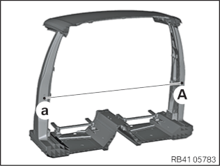
Frame Reference Dimensions For The B-Pillar 3-Dimensional