Adjusting cylinder bank 2 timings
Preliminary work
- Refer to CHECKING CAMSHAFT TIMING
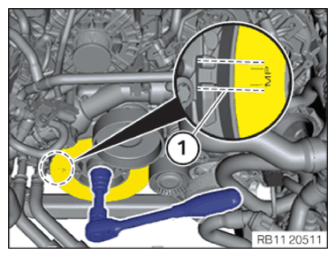
- Turn the engine clockwise on the central bolt until installation position (1) of vibration absorber (1) is aligned with the marks of the engine block.
- Adjust camshaft positions of bank 2.
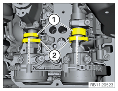
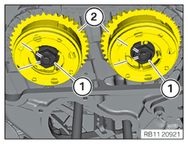
Cams (1) must be roughly in the position shown.
Ensure that increment wheels (2) point towards the exhaust camshaft bearing cap and the intake camshaft bearing cap.
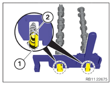
- Ensure that the ground surfaces of camshafts (2) point up.
- Make sure that the rounded surfaces (1) point downwards to the cylinder head.
- Check and evaluate the timing once again.
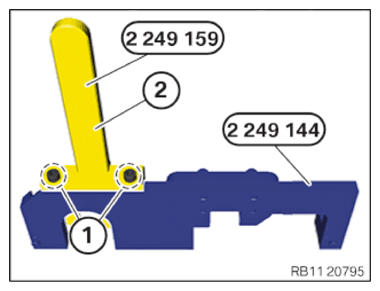
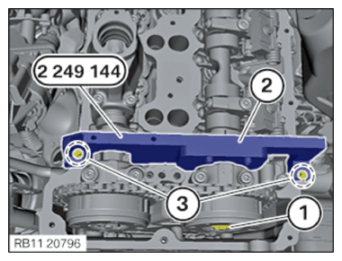
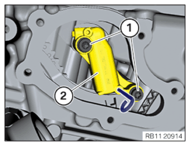
- Release screws (1) on special tool 2 249 144 from the set of special tools 2 249 117.
- Remove the special tool 2 249 159 (2 ).
- Counter the VANOS central valves only with special tools from the set of special tools 2 249 117.
- Turn the engine at central bolt until the special tool 2 249 144 (2) can be positioned on the intake camshaft.
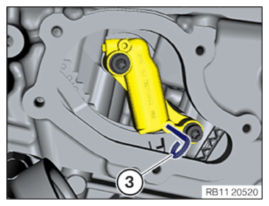
- Tighten the screws in the cylinder head cover (3) with the special tool 2 249 144 (2).
| SWZ2249117 | ||
|---|---|---|
| Screw M6 | Tightening torque | 10 Nm |
- Loosen VANOS central valve (1).
The VANOS central valve (1) may not be screwed out fully.
Manually push VANOS central valve (1) as far as it will go.
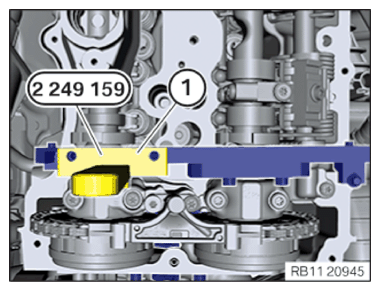
- Rotate the engine on the central bolt until the special tool (1) 2 249 159 can be positioned on the exhaust camshaft.
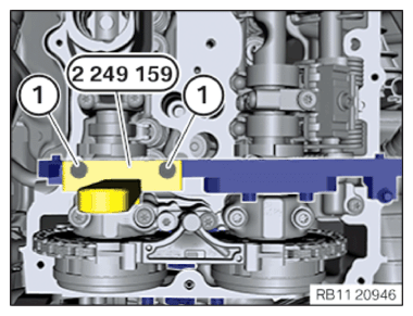
- Fasten the special tool 2 249 159 with screws (1).
- Tighten down screws (1).
| SWZ2249117 | ||
|---|---|---|
| Screw M6 | Tightening torque | 10 Nm |
- The VANOS central valves may only be countered with special tools from the set of special tools 2 249 117.
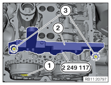
- Secure the special tool 2 249 117 (2) with screws of the cylinder head cover (3).
- Loosen VANOS central valve (1).
The VANOS central valve (1) may not be screwed out fully.
Manually push VANOS central valve (1) as far as it will go.
- Make straight marks on the VANOS central valves (1) and the VANOS adjusters (2) in the area of the hexagon head.
The angle must be 60°.
- Release the VANOS central valves (1) in the area of the hexagon head in a counterclockwise direction until the upper mark of the VANOS central valve matches with the lower mark.
The rotational angle must be 60°.
- Turn the engine counter-clockwise by 90° at central bolt.
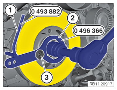
Ensure that special tools (1) 0 493 882 (11 9 190) and 0 496 366 (11 8 570 ) (2) do not collide with the other components.
- Remove the special tool 0 496 366 (11 8 570) (2).
- Position the special tool (1) 0 493 882 (11 9 190) in the recess on the engine block.
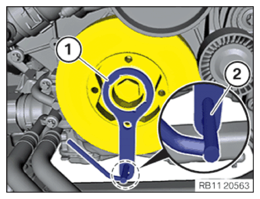
- Turn the engine on the central bolt clockwise until the special tool 0 493 882 (11 9 190 ) (1) lies against special tool 0 496 366 (11 8 570) (2).
- Tighten special tool 0 496 366 (11 8 570 ) (2) hand-tight to the vibration absorber with a screw of the belt pulley (3).
- Remove special tool (1) 0 493 882 (11 9 190).
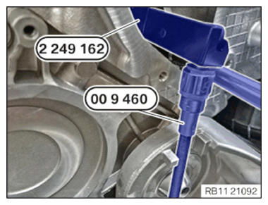
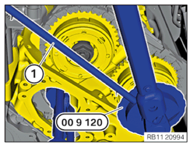
- Check the preload on the special tool 2 249 162 with the special tool 0 496 778 (00 9 460 ) with 0.6 Nm.
The flexible shaft on special tool 0 496 778 (00 9 460 ) must not come in contact with any other components, as otherwise the torque value is falsified.
| Preload timing chain | ||
|---|---|---|
| tightening torque | 0.6 Nm | |

- Tighten VANOS central valves (1).
| VANOS central valve initial torque | ||
|---|---|---|
| VANOS central valve | Joining torque | 5 Nm |
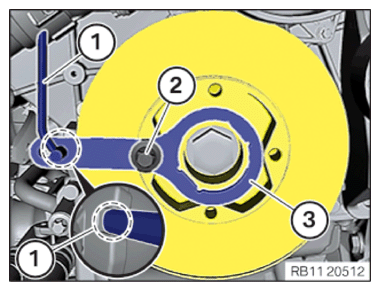
- Turn engine on the central bolt until the special tool is aligned with the struts on the engine block.
- The special tool 0 496 366 (11 8 570) (3) must be fastened to the vibration absorber with a screw from the belt pulley (2).
- Slide the crankshaft in the installation position with the special tool 0 493 882 (11 9 190) (1) on the bars and fix it.
- Tighten VANOS central valves (1).
| VANOS central valve second tightening | ||
|---|---|---|
| VANOS central valve | Joining torque | 30 Nm |
| Joining torque | 50 Nm | |
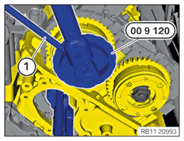
- Position special tool 0 490 504 (00 9 120) (1) on the VANOS exhaust central valve.
The magnetic foot of the special tool 0 490 504 (00 9 120) must be attached to a magnetic component in the engine compartment.
- The flexible element of the special tool 0 490 504 (00 9 120) (1) may not collide with other components.
- Set the angle of rotation on the special tool 0 490 504
(00 9 120) to zero.
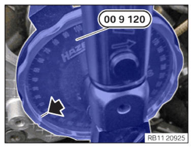
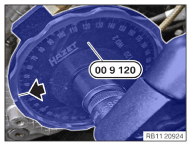
- Tighten the VANOS exhaust central valve until the needle on special tool 0 490 504 (00 9 120) is at 30°.
| VANOS central valve third tightening | ||
|---|---|---|
| VANOS central valve | Angle of rotation | 30° |
- Position special tool 0 490 504 (00 9 120 ) (1) on the VANOS central intake valve.
The magnetic foot of the special tool 0 490 504 (0 0 9 120) must be attached to a magnetic component in the engine compartment.
- The flexible element of the special tool 0 490 504 (00 9 120) (1) may not collide with other components.
- Set the angle of rotation on the special tool 0 490 504 (00 9 120 ) to zero.
- Tighten VANOS central intake valve until the needle on the special tool 0 490 504 (00 9 120 ) is at 30°.
| VANOS central valve third tightening | ||
|---|---|---|
| VANOS central valve | Angle of rotation | 30° |

- Loosen screws (2).
- Remove the special tool 2 249 117 (1).
- Remove special tool 0 493 882 (11 9 190) (1).
- Release the screw of the belt pulley (2).
- Remove special tool 0 496 366 (11 8 570) (3).
- Turn the engine clockwise on the central bolt with 2 crankshaft revolutions until installation position (1)° of vibration absorber (1)° is aligned with the struts of the engine block.
- Check the camshaft positions of cylinder bank 2.
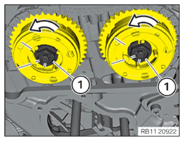
The cams (1) must be in the position shown.
Increment wheels (2) must form a straight line to the exhaust camshaft bearing cap and the intake camshaft bearing cap.

- Ensure that the ground surfaces of camshafts (1) point up.
- Make sure that the rounded surfaces (1) point downwards to the cylinder head.
- Check and evaluate the timing once again.
- Position special tool 0 496 366 (11 8 570) (3) on the vibration absorber.
- Position special tool 0 493 882 (11 9 190) (1) in special tool 0 496 366 (11 8 570 ).
The special tool 0 493 882 (11 9 190) (1) must not be inserted very far as it may collide with other components while turning the crankshaft.
- Position reversible ratchet.
- Rotate engine on the central bolt until the special tool lines up with the engine block marks.
- Tighten special tool 0 496 366 (11 8 570 ) (3) hand-tight to the vibration absorber with a screw of the belt pulley (2).
- Slide the crankshaft in the installation position with the special tool 0 493 882 (11 9 190) (1) at the marks and fix it.
Check
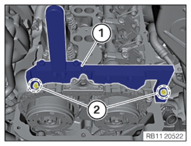
- Position special tool 2 249 117 (1) on the camshafts of cylinder bank 2.
- Check whether the camshafts can be fixed with the special tool 2 249 117 (1).
- Check if the special tool 2 249 117 can be brought in contact with the cylinder head using the two screws of the cylinder head cover (2).
Result
» The camshafts can be fastened.
Measure
- Loosen screws (2).
Remove the special tool 2 249 117 (1 ). Continue the repair in the next step.
Result
» The camshafts cannot be fastened. Measure
- Adjust the timings of cylinder bank 2.
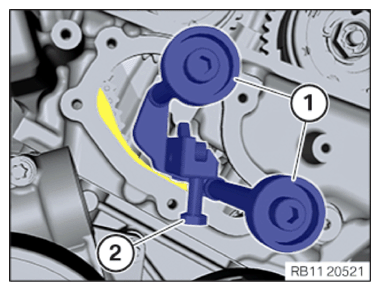
- Release timing chain on the special tool 2 249 162 by turning the hexagon screw (2).
- Release special tool 2 249 162 in area (1) and remove.
- Feed in and position the hydraulic chain tensioner (2).
- Tighten down screws (1).
| Chain tensioner to cylinder head | ||
|---|---|---|
| screw | Tightening torque | 13 Nm |
- Remove the special tool 0 491 012 (11 4 120 ) or transportation retainer (3) from the bore.
- Loosen screws (2).
- Remove the special tool 2 249 117 (1).
- Remove special tool 0 493 882 (11 9 190) (1).
- Release the screw of the belt pulley (2).
- Remove special tool 0 496 366 (11 8 570) (3).