11 42 200 Removing and installing/replacing the oil feed line for the exhaust turbocharger N63O2 (M550i xDrive 2018-2019)
Special tools required:
- 11 7 020
- 11 0 390
- 2 359 116
- 2 450 691
- 32 1 260
Only perform this repair after the engine has cooled down.
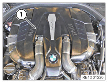
Unclip acoustic cover (1) from the top and remove.
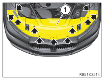
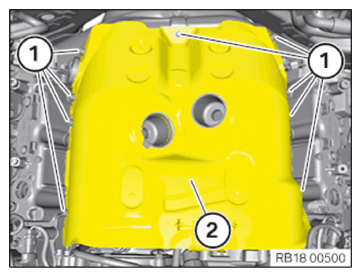
Release all expanding rivets (arrows).
Remove cover (1).
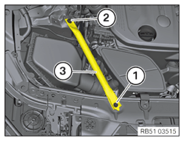
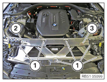
Unfasten screws (1 and 2).
Remove left and right strut (3).
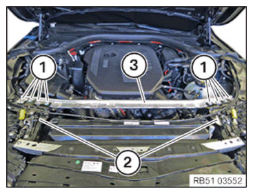
Unscrew the screws (1).
Attach the cable linkage (2).
Feed out the front cross connection (3) toward the top.
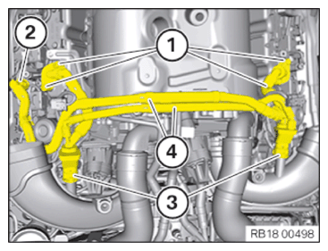
Unscrew the screws (1).
Lift the support (2) of the left hood lock slightly and feed out the top rear cross connection (3) to the rear.
Lift the support (2) of the right hood lock slightly and feed out the top rear cross connection (3) to the rear and remove it.
Unlock the connector (1) of the Lambda oxygen sensor and detach.
Release the cable (2) of the Lambda oxygen sensor from the clamps.
Unlock and detach the connector (1) of the hot film air mass meter.
Release clamps (2).
Detach the intake filter housing (3) from rubber mounts in upward direction.
Detach the intake filter housing (3) from the clean air pipe.
Feed out the cable of the Lambda oxygen sensors through the opening on the intake filter housing (3).
Remove intake filter housing (3).
Release the detents (arrows) of the unfiltered-air duct (1) at the front on the air duct.
Pull the unfiltered-air duct (1) to the rear out of the air duct.
Feed out the unfiltered-air duct (1) upwards and remove.
Release the detents (arrows) of the unfiltered-air duct (1) at the front on the air duct.
Pull the unfiltered-air duct (1) to the rear out of the air duct.
Feed out the unfiltered-air duct (1) upwards and remove.
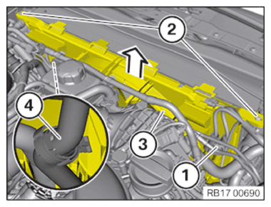
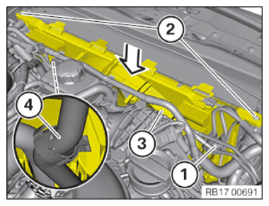
Unlock the plug connection (1) for the electric fan and detach.
Unscrew the screws (2).
Unclip the coolant hoses (4) from the fan cowl (3).
Feed out fan cowl (3) towards top and remove.
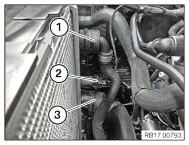
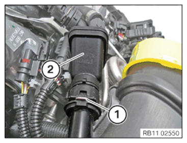
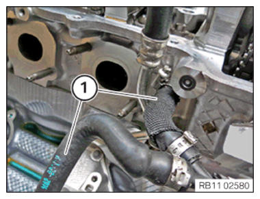
Unlock coolant line (1) and release.
Unlock coolant line (3) and release.
Catch and dispose of escaping coolant.
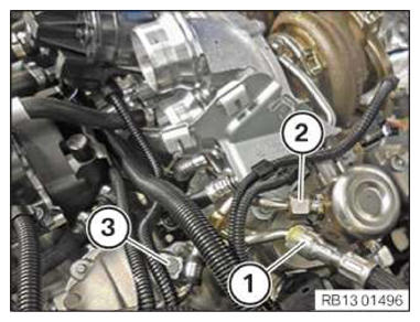
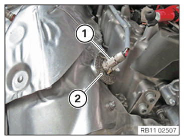
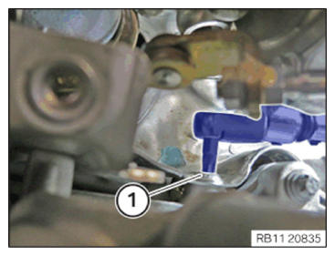
Unlock and detach the fuel supply line (1).
Release union nut (2).
Unscrew nut (3).
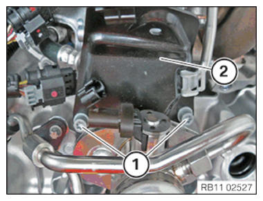
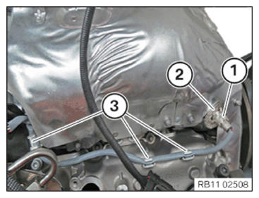
Unscrew the screws (1).
Remove heat shield (2).
Installation note:
The screw threads of the new oxygen control/monitoring sensors are already coated with NEVER-SEEZ compound (refer to the appropriate BMW parts catalogue).
If a lambda control/oxygen sensor monitor is to be reused, apply a thin and even coating of NEVER-SEEZ compound to the screw thread only.
The part of the lambda control/oxygen sensor monitor which projects into the exhaust pipe system (sensor ceramics) must not be cleaned and not coated with lubricant.
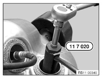
Release the Lambda oxygen sensor using special tool 11 7 020 and a torque wrench (1).
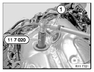
Detach the lambda oxygen sensor using a special tool 11 7 020.
Release the heat protection clamp (1).
Remove the wire ring (2).
Release the heat protection clamp (1).
Remove the wire ring (2).
Unclip oxygen sensor cable (3).
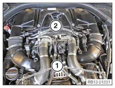
Unscrew the screws (1).
Unlock and detach engine vent line (2).
Unlock the engine ventilation line (3) and detach from the clean air pipe.
Release and remove engine ventilation line (4) from the cylinder head cover.
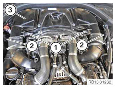
Remove screw (1).
Remove heat shield (2) upwards.
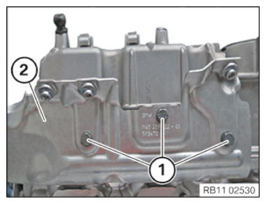
Unscrew the screws (1).
Remove the heat shield (2) at cylinder head cover 5 to 8.
Attention!
Risk of damage on the plastic fitting aids.
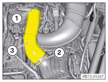
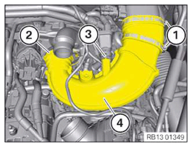
Open the snap fastener clutch (1) with a suitable screwdriver.
Open the circlip (2) with a suitable tool.
Remove the charge air hose (3).
Attention!
Risk of damage on the plastic fitting aids.
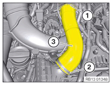
Open the snap fastener clutch (1) with a suitable screwdriver.
Open the circlip (2) with a suitable tool.
Remove the charge air hose (3).
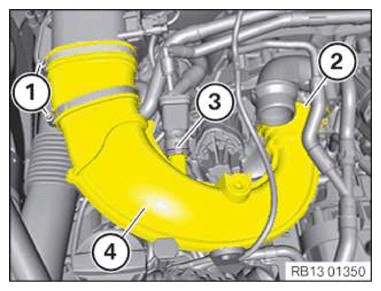
Unlock the retaining clip (1) from the fresh air duct (2).
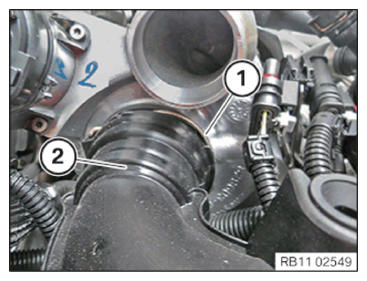
Unlock the clamp (1) of the crankcase ventilation system (2).
Release the detents (2) of the fresh-air duct (4) at the front on the air duct.
Detach the crankcase ventilation system (3).
Feed out clean air duct (4) and remove.
Release the detents (2) of the fresh-air duct (4) at the front on the air duct.
Unlock the clamp (1) of the crankcase ventilation system (2).
Feed out clean air duct (4) and remove.
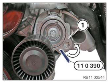
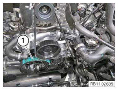
Pretension belt tensioner in direction of arrow.
Secure belt tensioner (1) in place with special tool 11 0 390.
Remove drive belt (1).
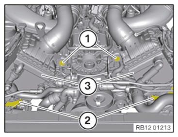
Unscrew the screws (1).
Release locks (2).
Partially detach the charge air cooler (3) and set it to the side.
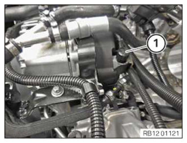
Detach cover (1) and loosen nut underneath.
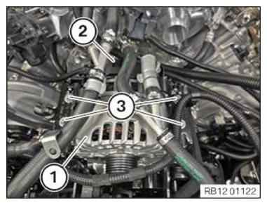
Disconnect positive battery cable from alternator.
Unlock the connector (2) and disconnect it from the alternator (1).
Release the screws (3) and remove the holder from the alternator (1).
Feed out alternator (1) and remove.
Release the banjo bolt (1) of the coolant line.
Remove screw (1).
Feed out the coolant line (2) downwards.
Remove screw (1).
Release banjo bolt (1).
Set oil feed line (2) to one side.
Remove screw (1).
Release banjo bolt (1).
Set oil feed line (2) to one side.
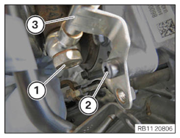
Release banjo bolt (1).
Remove screw (2).
Place the coolant line (3) aside.
Release the coolant lines (1) in the V-area at left and right.
Remove screw (1).
Remove screw (1).
Remove screw (1).
Remove screw (1).
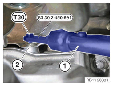
Required special tool 2 359 116 and 2 450 691 with a torque wrench (1) with changeable socket head.
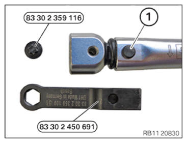
Prepare special tool.
Prepare the Torx T30 from special tool 2 359 116 and insert with special tool 2 450 691.
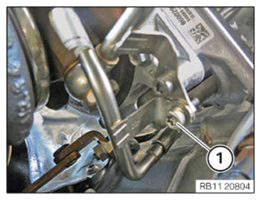
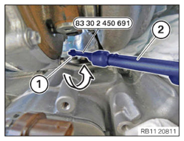
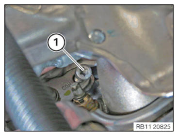
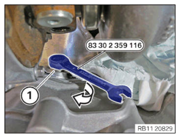
Release the screw (1) with special tool 2 450 691 and a suitable socket wrench (2).
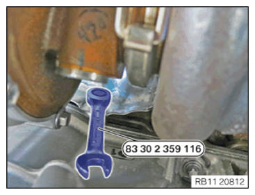
Release the screw with a ratchet wrench 2 359 116.
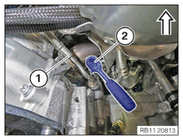
Push the heat shield upward in arrow direction and hold.
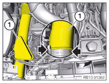
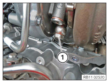
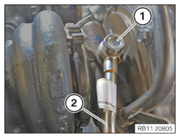
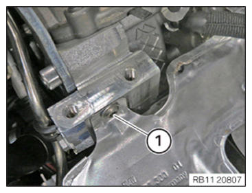
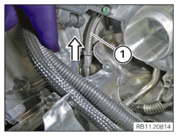
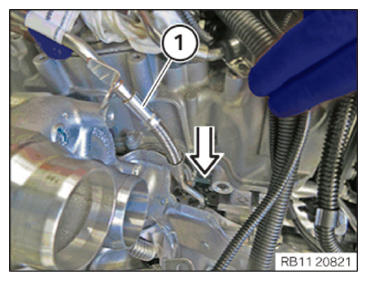
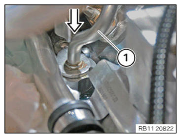
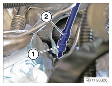
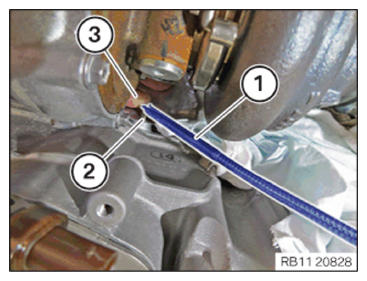
Release the screw for the oil feed line (1) with 1/4 inch ratchet (2).
Release the oil feed line (1) in direction of arrow.
Installation note:
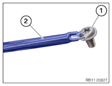
Grease the O-ring (1) with assembly paste (83 23 9 407 778).
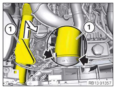
Mount the oil feed line (2) in direction of arrow.
Mount the oil feed line (1) in direction of arrow.
Installation note:
Put down the V-area with a suitable cloth.
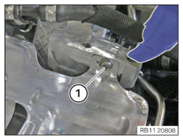
Mount the oil feed line with a screw (1).
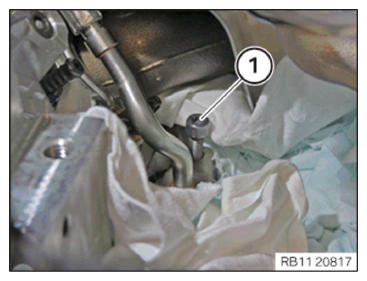
Fasten the screw (1) with a suitable 1/4 inch torque wrench.
Tightening torque: 10 Nm.
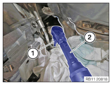
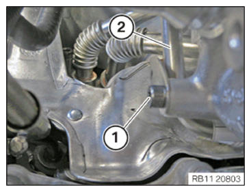
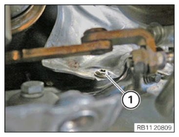
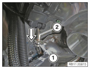
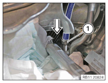
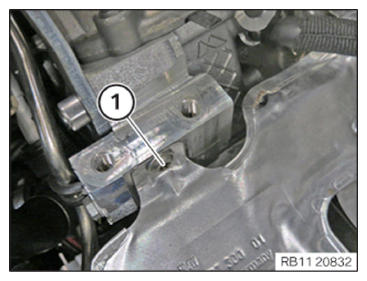
Release the screw (1) of the oil feed line with a universal joint (2).
Remove the screw (1) with a magnet.
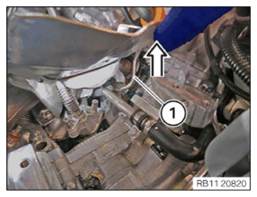
Remove the oil feed line (1) in an upward direction.
Installation note:
Grease the O-ring with assembly paste (83 23 9 407 778).
Mount the oil feed line (1) in direction of arrow.
Mount the oil feed line (1) in direction of arrow.
Use a magnet (2) as an aid for joining the screw (1) on the oil feed line on cylinder bank 2.
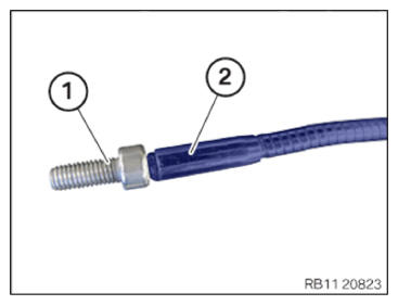
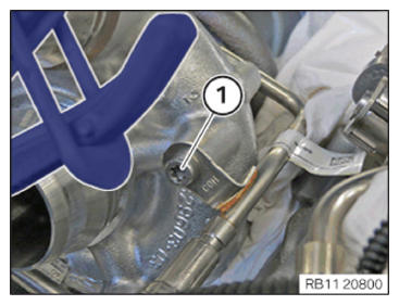
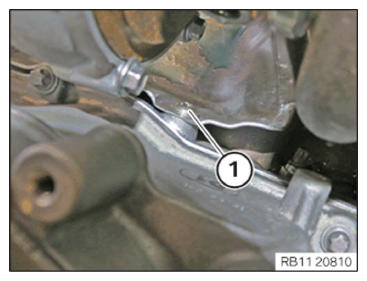
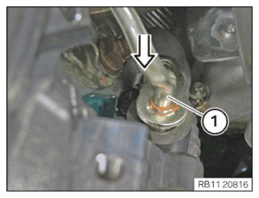
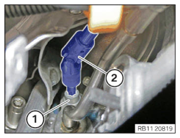
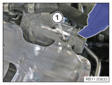
Position the bolt (1) on the screw connection of the oil feed line, see arrow.
Bolt (1) is positioned and can now be screwed in.
Screw and fasten the threaded connection with a T30 socket in combination with a wobble joint (2).
Tightening torque: 10 Nm.
Join the bolt (1) of the screw connection for the heat shield on bank 1.
Join the bolt (1) of the screw connection for the heat shield on bank 2.
Join the bolt (1) of the screw connection for the heat shield on bank 1.
For the threaded connection on the heat shield on cylinder head of cylinder bank 2, the bolt (1) must be fastened using a hand picker (2) as a installation aid.
See illustration.
Join the bolt (2) of the screw connection for the heat shield on bank 2.
Position the installation aid (1) with the screw (2).
Using the index finger (3), the screw (1) can be secured from falling down.
Secure screw (1) with special tool 2 359 116.
Installation note:
The torque must be adjusted with the application of special tool 2 450 691.
Using the torque wrench (1) in combination with special tool 2 450 691 with wrench socket set T30, fasten the screw (2) with 9 Nm.
Tighten screw (1) using 10 Nm.
Tighten screw (1) using 10 Nm.
Installation note:
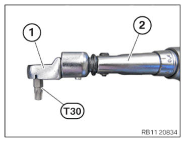
The following tool must be prepared for the threaded connection of the heat shield on the exhaust turbocharger of cylinder bank 1.
Prepare the insert (1) e.g. (Hazet 6420b) with a socket T30 and a suitable torque wrench (2).
Tighten screw (1) using 10 Nm.
Position the coolant line (2) on the exhaust turbocharger.
Add screws (1).
Installation note:
Replace sealing rings.
Join the banjo bolt (1) of the coolant line.
Tightening torque: 35 Nm.
Secure coolant line (2).
Tighten screw (1) using 10 Nm.
Add screws (1).
Installation note:
Replace the banjo bolt and sealing rings.
Position oil feed line (2).
Tighten banjo bolt (1).
Tightening torque: Join to 8 Nm and final tighten with a 70° angle of rotation.
Tighten screw (1) using 10 Nm.
Installation note:
Replace the banjo bolt and sealing rings.
Join the banjo bolt (1) for the oil feed line (2).
Installation note:
Replace the seals.
Join the banjo bolt (1).
Fasten the coolant line (3) with the screw (1) to 10 Nm.
Tighten banjo bolt (1) using 35 Nm.
Installation note:
Replace the banjo bolt and sealing rings.
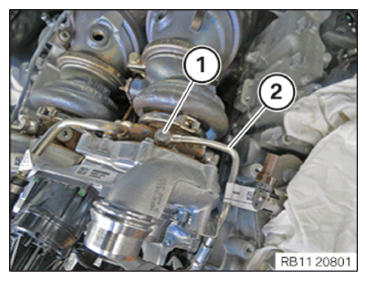
Join the oil feed line (2) with the banjo bolt (1) on the exhaust turbocharger.
Tighten screw (1) using 10 Nm.
Tighten banjo bolt (1).
Tightening torque: Join to 8 Nm and final tighten with a 70° angle of rotation.
Insert and fasten the coolant lines (1).
Install the heat shield (2) at cylinder head cover 5 to 8.
Secure screws (1) with 10 Nm.
Join the union nut (2) with 10 Nm and secure with 30 Nm final torque.
Insert the fuel supply line (1).
Tighten screw (3) using 10 Nm.
Install heat shield (2).
Secure screws (1) with 10 Nm.
Install alternator (1).
Install the holder on the alternator (1) and tighten the screws (3).
Tightening torque: 22 Nm.
Connect the positive battery cable to the alternator.
Tighten nut.
Tightening torque: 19 Nm.
Unplug the cover (1) on the positive terminal of the alternator.
Position the charge air cooler (3).
Let the locks (2) audibly engage.
Tighten down screws (1).
Secure screws (1) with 8 Nm.
Place the drive belt (1) as shown in the graphic.
Pretension the tensioning pulley (1), remove special tool 11 0 390.
Insert the coolant line (1) and check for secure fit.
Insert the coolant line (3) and check for secure fit.
Insert and install the fan cowl (3) into the guides in arrow direction.
Secure the coolant hose (4) on the fan cowl (3).
Plug connection (1) must audibly engage.
Tighten screws (2) to 5.5 Nm.
Position the heat shield (2).
Tighten all screws (1) using 10 Nm.
Installation note:
The screw threads of the new oxygen control/monitoring sensors are already coated with NEVER-SEEZ compound (refer to the appropriate BMW parts catalogue).
If a lambda control/oxygen sensor monitor is to be reused, apply a thin and even coating of NEVER-SEEZ compound to the screw thread only.
The part of the lambda control/oxygen sensor monitor which projects into the exhaust pipe system (sensor ceramics) must not be cleaned and not coated with lubricant.
Fasten the Lambda oxygen sensor using special tool 11 7 020 and a torque wrench (1) to 50 Nm.
Fasten the Lambda oxygen sensor using special tool 11 7 020 and a torque wrench (1) to 50 Nm.
Position the wire ring (2).
Insert the heat protection clamp (1).
Installation note:
Check the O-rings for damage, replace if necessary.
Connect engine ventilation line (4) to the cylinder head cover.
Secure screws (1) with 10 Nm.
Thread in clean air pipe (4) and install.
Unlock the engine ventilation line (3) and connect to the clean air pipe (4).
Thread in clean air pipe (4) and install.
Unlock the engine ventilation line (3) and connect to the clean air pipe (4).
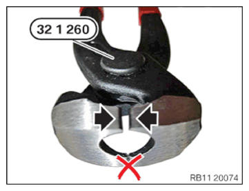
Use the special tool 32 1 260 on the side with the opening for joining the clamps (see graphic).
The circlip is joined correctly when the gap is smaller than 1 mm.
Attention!
Risk of damage on the plastic fitting aids.
Insert the charge air hose (3).
The locking mechanism on the charge air hose (3) must engage audibly.
Replace clamp (2).
Fasten the circlip (2) of special tool 32 1 260.
Attention!
Risk of damage on the plastic fitting aids.
Insert the charge air hose (3).
The locking mechanism on the charge air hose (3) must engage audibly.
Replace clamp (2).
Fasten the circlip (2) of special tool 32 1 260.
Feed in the left and right unfiltered-air duct (1).
Lock the unfiltered-air duct (1) in the air duct at the front (arrows).
Feed in the cable of the Lambda oxygen sensor through the opening on the intake filter housing (3).
Install the intake filter housing (3) and attach to the rubber mounts.
Connect the clean air pipe to the intake filter housing (3) and secure it with the circlips (2).
Fasten the circlips (2) with 3 Nm.
Connect the connectors (1) of the hot film air mass meter; the connectors must audibly engage.
Fasten the cable (2) of the Lambda oxygen sensor on the clamps.
Connect the connectors (1) of the Lambda oxygen sensors; the connectors must audibly engage.
Position the acoustic cover (1) and clip in rubber mount.
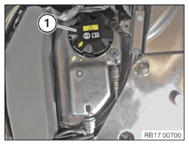
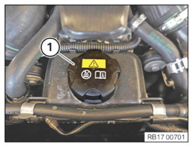
Open the coolant lid (1) for the high temperature.
Prepare the vacuum filling equipment according to the diagram.
Before starting the automatic cooling system bleeding procedure, make sure that both coolant circuits are filled. The cooling system bleeding procedure is automatically started simultaneously for both coolant circuits. If the cooling system bleeding procedure is started while one of the coolant circuits is empty, there is a danger of damage to the electric coolant pump when running it dry. Make sure that terminal 15 is not disconnected for the bleeding procedure. Switch on low beam headlights and hazard warning lights. If the low beam headlights and hazard warning lights are not switched on, the ignition (terminal 15) will switch off automatically after a certain period of time and interrupt the bleeding procedure.
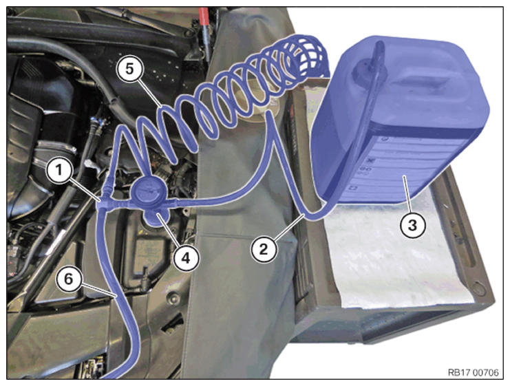
- Vacuum filling equipment with pressure gauge and shutoff valves.
- Filling hose
- Fluid tank with coolant.
- Venturi nozzle.
- Compressed air connection (maximum of 6 bar)
- Exhaust hose (route the exhaust hose into a collecting vessel)
Required filling capacity of cooling system is 9.2 liters.
Open the coolant lid (1) for the low temperature.
Prepare the vacuum filling equipment according to the diagram.
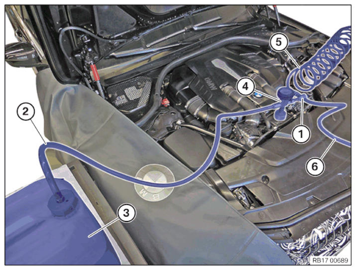
Before starting the automatic cooling system bleeding procedure, make sure that both coolant circuits are filled. The cooling system bleeding procedure is automatically started simultaneously for both coolant circuits. If the cooling system bleeding procedure is started while one of the coolant circuits is empty, there is a danger of damage to the electric coolant pump when running it dry. Make sure that terminal 15 is not disconnected for the bleeding procedure. Switch on low beam headlights and hazard warning lights. If the low beam headlights and hazard warning lights are not switched on, the ignition (terminal 15) will switch off automatically after a certain period of time and interrupt the bleeding procedure.
- Vacuum filling equipment with pressure gauge and shutoff valves.
- Filling hose
- Fluid tank with coolant.
- Venturi nozzle.
- Compressed air connection (maximum of 6 bar)
- Exhaust hose (route the exhaust hose into a collecting vessel)
Close the lid (1) of the coolant expansion tank (low temperature coolant circuit).
Start bleeding routine.
- Open the bleeder screw on the coolant expansion tank for the high-temperature coolant circuit and close it again after approx. 10 s.
- The bleeder screw may be closed before the 10 s have elapsed when coolant emerges.
- Adjust the fill level in the coolant expansion tank of the high-temperature coolant circuit to the maximum mark.
- Close the sealing cap (1) on the coolant expansion tank of the high-temperature coolant circuit.
- Connect the battery charger.
- Close driver's seat belt.
- Turn on ignition by quickly operating the START-STOP button three times.
- Adjust the heating to the maximum temperature and the blower to the lowest setting.
- Floor the accelerator pedal and hold for 15 s. The automatic cooling system bleeding procedure is initiated.
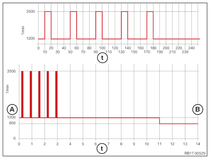
- Start engine. The idle speed is automatically increased to 1200 RPM.
- Actuate the accelerator pedal to approximately 3500 rpm and hold the engine speed for 10 s.
- Hold idle speed for 30 s.
- Actuate the accelerator pedal to approximately 3500 rpm and hold the engine speed for 10 s.
- Hold idle speed for 30 s.
- Actuate the accelerator pedal to approximately 3500 rpm and hold the engine speed for 10 s.
- Hold idle speed for 30 s.
- Actuate the accelerator pedal to approximately 3500 rpm and hold the engine speed for 10 s.
- Hold idle speed for 30 s.
- Actuate the accelerator pedal to approximately 3500 rpm and hold the engine speed for 10 s. The cooling system bleeding procedure has finished approximately 11 min after the engine starts. The engine speed drops to the idle speed again.
- Let the engine warm up at idle until the coolant has reached a temperature of 100°C. The temperature display in the instrument cluster (KOMBI) is in the center position.
- Actuate the accelerator pedal to approximately 3500 rpm and hold the engine speed for 10 s.
- Hold idle speed for 30 s.
- Actuate the accelerator pedal to approximately 3500 rpm and hold the engine speed for 10 s.
- Hold idle speed for 30 s.
- Actuate the accelerator pedal to approximately 3500 rpm and hold the engine speed for 10 s.
- Hold idle speed for 30 s.
- Actuate the accelerator pedal to approximately 3500 rpm and hold the engine speed for 10 s.
- Hold idle speed for 30 s.
- Actuate the accelerator pedal to approximately 3500 rpm and hold the engine speed for 10 s.
- Switch off engine.
- Allow the engine to cool down.
- Adjust the fill level in the coolant expansion tank of the high-temperature coolant circuit to 100 ml above the maximum mark.
A = increased idle speed B = cooling system bleeding procedure ended t = time.