Adjusting the right-hand camber
- Only adjust the camber on the right if the measured value for the camber on the right is outside the tolerance.
Remove front right wheel
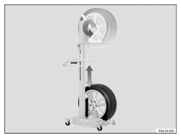
Remove the WHEEL
NOTE: TECHNICAL INFORMATION
A wheel lifter is recommended for easier wheel removal and installation without exertion (see the applicable BMW Parts Catalog). - In vehicles with M Carbon ceramic brake: It is essential to use the wheel lifter to remove the wheel.
This process is intended to prevent damage to the brake disc.
- If several wheels are removed simultaneously:
Use a piece of chalk to mark on each tire the axle and side on which the corresponding wheel is fitted.
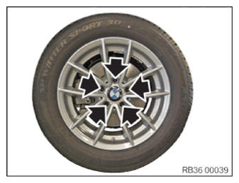
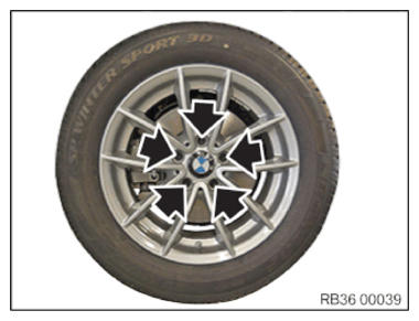
- Release the lug bolts (arrows) crosswise and remove the wheel.
- For releasing and tightening lug bolts with the security code: Use the correct adapter from the set of special tools 0 492 518 (36 1 300).
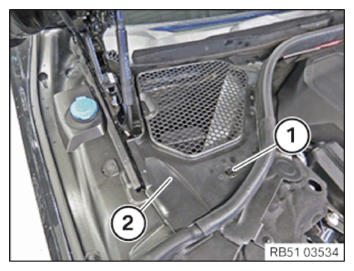
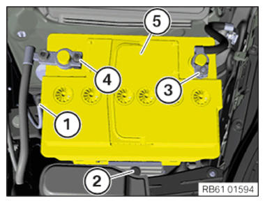
Remove the cover of the rear right engine compartment
- Loosen the lock (1).
- Remove the cover (2).
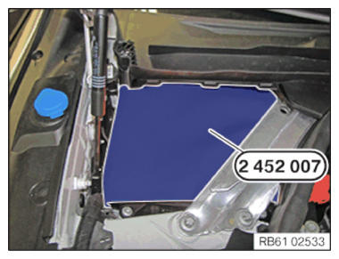
Covering the vehicle battery
WARNING: Unprotected battery terminals.
Risk of short circuits! Risk of fire!- Cover the vehicle battery.
NOTE: The following step(s) must be performed if the listed component(s) is/are installed.Cover the vehicle battery with the special tool 2 452 007 as shown.
If installed: Removing the auxiliary battery for vehicle electrical system support in the engine compartment (additional work FRU number: 61 21 903)
- Remove auxiliary battery (5).
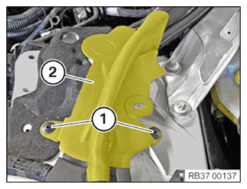
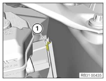
Detach the spring strut in front
- Loosen the rivet (1).
- Remove the cover (2).
- Loosen screws (1).
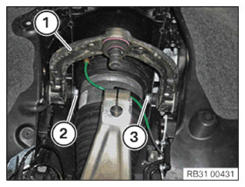
Remove top wishbone
- Release the nut (1) of the front screw connection above at the upper wishbone on shock tower in the engine compartment.
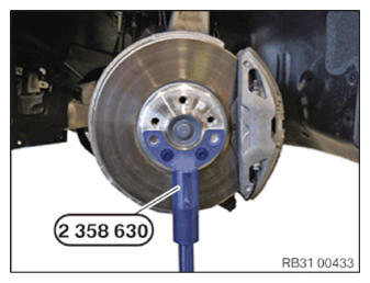
Support swivel bearing
- Secure special tool 2 358 630 to drive flange with lug bolts.
- Support the swivel bearing using the special tool 2 358 630 and the universal jack.
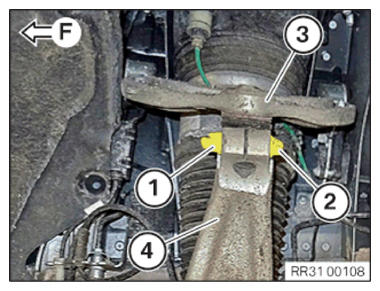
- Release nut (1).
- Pull out screw (2).
- Release upper wishbone (3) from the swivel bearing (4).
(F) = driving direction
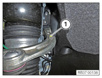
- Undo nut (1) of the ride height sensor on the upper wishbone.
- Loosen screw (3).
- Pull the spring strut outwards slightly until the screws (2) and (3) can be pulled out.
- Pull out screws (2) and (3).
- Remove top wishbone (1).
Install top wishbone
- Replace the clip nut (1) of the rear screw connection of the upper wishbone on the body.
Parts: Clip nut
- Position the upper wishbone (1).
- Replace screws (2) and (3).
Parts: Screws
- Slight pull the spring strut outwards and install screws (2) and (3).
- Replace nut (1).
Parts: Nut
- Hand-tighten the nut (1) of the front screw connection on the upper wishbone on the shock tower in the engine compartment.
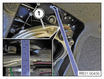
- Set the normal position of the upper wishbone (1).
- Set the lower edge of the upper wishbone (1) to the bodywork vertically to 100 mm.
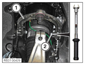
- Replace the screw (2).
Parts: Screw
- Tighten screw (2) of the upper wishbone (1) using torque wrench and open-end wrench insert.TIGHTENING TORQUES SPECIFICATION
Upper wishbone to body M10
Replace screw and nut.Tightening torque 54 Nm - Replace nut (1).
Parts: Nut
- Tighten nut (1).TIGHTENING TORQUES SPECIFICATION
Upper wishbone to body M10
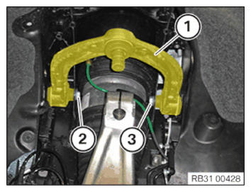
Replace screw and nut.Tightening torque 54 Nm - Position upper wishbone (3) on the swivel bearing (4).
- Replace screws (2) and nuts (1).
Parts: Bolt, nut
- Insert screw (2).
The screw (2) must be positioned in the groove of the tappet of the upper wishbone (3).
(F) = driving direction
- Tighten nut (1).TIGHTENING TORQUES SPECIFICATION
Upper wishbone to swivel bearing M10
Replace screw and nut.Tightening torque 56 Nm - Position jointed rod on upper wishbone.
- Replace nut (1).
Parts: Nut
- Tighten nut (1).TIGHTENING TORQUES SPECIFICATION
Jointed rod ride height sensor on wishbone M6 Tightening torque 8 Nm - Lower the universal jack and put it away.
- Remove special tool 2 358 630.
Attach the front spring strut
- Position the spring strut on the strut-tower.
- Replace screws (1).
Parts: screw
- Tighten the screws (1).TIGHTENING TORQUES SPECIFICATION
Front spring strut support bearing to body M8
Replace screws.Tightening torque 28 Nm - Position the cover (2).
- Secure the rivet (1).
If installed: Installing the auxiliary battery for the vehicle electrical system support in the engine compartment (additional work FRU number: 61 21 903)
- Install auxiliary battery (5).
For ADDITIONAL INFORMATION , see: Remove and install the auxiliary battery of vehicle electrical system support.
Install the rear right engine compartment cover
Remove the battery COVER
NOTE: The following step(s) must be performed if the listed component(s) is/are installed. - Remove the special tool 2 452 007 from the battery.
- Install the cover (2).
- Lock the lock (1).
Mounting the wheel
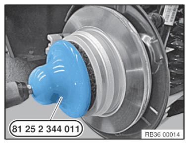
NOTE: TECHNICAL INFORMATION The contact surface between the brake disc and the wheel rim must be clean and free from oil and grease. There is otherwise a risk of the wheel becoming loose at a later time. - Remove dirt, grease residues and corrosion from the contact surface with a drill and the special tool 2 344 011.
- Do not operate special tool 2 344 011 with an impact screwdriver.
- Degrease the contact surfaces with the universal cleaner (see the applicable BMW Part Catalog).
- In the event of grease residues in the area of the wheel bolt holes, remove and clean the brake disk.
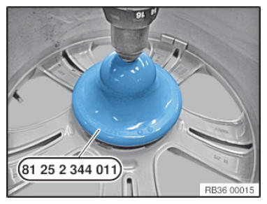
- Remove dirt, grease residues and corrosion from the contact surface with a drill and the special tool 2 344 011
.
Do not operate special tool 2 344 011 with an impact screwdriver.
- Degrease the contact surfaces with the universal cleaner (see the applicable BMW Parts Catalog).
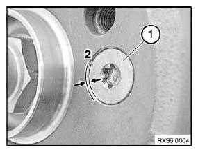
- Check if the mounting bolt (1) has been fitted correctly for the brake disk.
The mounting bolt (1) for the brake disk cannot protrude on the contact surface (2) between the brake disk and the rim.
TIGHTENING TORQUES SPECIFICATIONBrake disc to front wheel hub M8
Replace screw.Tightening torque 16 Nm TIGHTENING TORQUES SPECIFICATIONBrake disc to rear wheel hub M8
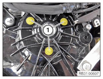
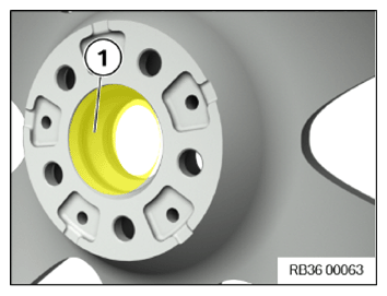
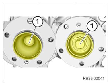
Replace screw.Tightening torque 16 Nm NOTE: TECHNICAL INFORMATION Do not grease the wheel hubs and wheel centering in models G80, G82 and G83. - Lightly grease the wheel centering (1) in the rim.CONSUMABLE - BRAKE BLOCK PASTE DESCRIPTION
Brake block paste
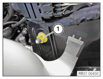
* TU = Trade Unit. TU numbers cannot be ordered! For invoicing purposes only.3 g, Bag 83192158851 100 g, Tube 83192158852 5 g, TU* 83230140233 NOTE: TECHNICAL INFORMATION Do not grease the wheel hubs and wheel centering in models G80, G82 and G83. - Apply a thin layer of grease to the front and rear wheel hubs (1) to protect against corrosion.CONSUMABLE - BRAKE BLOCK PASTE DESCRIPTION
Brake block paste
* TU = Trade Unit. TU numbers cannot be ordered! For invoicing purposes only.3 g, Bag 83192158851 100 g, Tube 83192158852 5 g, TU* 83230140233 NOTE: TECHNICAL INFORMATION A wheel lifter is recommended for easier wheel removal and installation without exertion (see the applicable BMW Parts Catalog). - In vehicles with M Carbon ceramic brake: The wheel lifter must be used to install the wheel.
This process is intended to prevent damage to the brake disc.
Check
- Check lug bolts for wear.
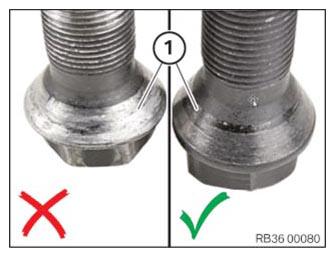
Result
» Spots (> 30%) of the bearing surface (1) of the taper on the screw head show silvery wear.
Measure
- Replace lug bolts.
Parts: Lug bolts
Never use an impact screwdriver or electric screwdriver to apply and tighten the lug bolts.
The rim must rest evenly against the brake disc.
In the case of non-original BMW lug bolts/wheel rims, it may be necessary to retighten the lug bolts on user account of setting properties (refer to the documentation from the manufacturer).
Do not apply oil to new lug bolts.
- Replace the corroded lug bolts (arrows).
Parts: Lug bolts
- Clean wheel bolts (arrows).
- Check lug bolts (arrows) and threads for damage, replace lug bolts (arrows) if necessary.
- Join and tighten the lug bolts (arrows).
| Lug bolts | ||
| M14/SW17 Screw in lug bolts and evenly tighten crosswise by hand in order to center the wheel rim. Tighten lug bolts to the prescribed tightening torque with a calibrated torque wrench in a crosswise sequence. Check all the lug bolts in the same order or retighten to the prescribed tightening torque again. |
Tightening torque | 140 Nm |
| Check | 140 Nm | |
Follow-up work
- Check the steering wheel straight-ahead DRIVING POSITION