Checking cylinder head for watertightness
Prerequisite
All valves are removed
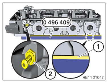
- Release the venting connector (2).
- Position special tool 0 496 409 (11 8 081) on cylinder head.
- The rubber layer (marked yellow) on the special tool 0 496 409 (11 8 081) must point to the cylinder head.
- The rigid side of the special tool 0 496 409 (11 8 081)
must face downwards.
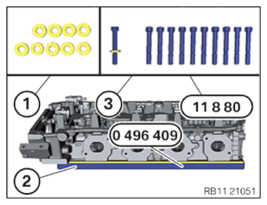
- To fasten the special tool 0 496 409 (11 8 081) , the washers (1) of the cylinder head bolt must be used.
- Fasten the special tool 0 496 409 (11 8 081)
(2) with the screws from the set of special tools 0 496 408 (11 8 080)
(3).
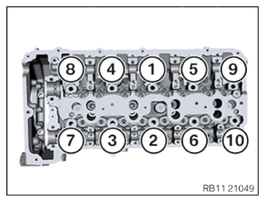
Observe the following tightening sequence.
- Tighten screws in the order (1) to (10).
TIGHTENING TORQUES SPECIFICATION
| Cylinder head to special tool | ||
|---|---|---|
| screw | Tightening torque | 25 Nm |
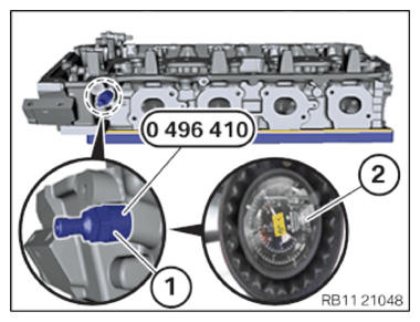
- Position the valve (1) from the set of special tools 0 496 408 (11 8 080) on the cylinder head and tighten.
TIGHTENING TORQUES SPECIFICATION
| Valve in cylinder head | ||
|---|---|---|
| valve | Tightening torque | 0.8 Nm |
- Apply the valve (1) with 3 bars of pressure (2).
- Dip the cylinder head into a water bath and check for leakage.
The water bath can be made easier with standard dish soap.
The formation of blisters indicate faults or cracks on the cylinder head.
- Relieve the pressure on the valve (1) with a tire pressure gauge (2).
- Disassemble the valve (1) from the set of special tools 0 496 410 (11 8 082)
.
- Release the screws of the device (1).
- Remove the device (1).
- Replace the venting connector (2).
Parts : Venting connector
- Tighten the venting connector (2).
TIGHTENING TORQUES SPECIFICATION
| Venting connector/special tool to cylinder head | ||
|---|---|---|
| M8x1 Replace the venting connector. |
Tightening torque | 15 Nm |
- Dry all openings on the cylinder head with compressed air.
- Coat the bearing positions of the camshaft with motor oil.