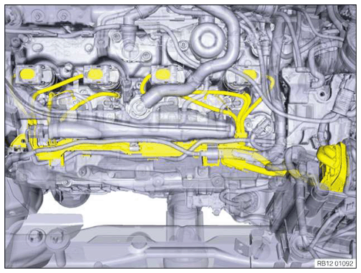
Installing the wiring harness section for the injectors of cylinders 1 to 4
NOTE:
RISK OF DAMAGE
Malfunction or failure of the DME.
Grounding points that are not screwed on may lead to malfunction or failure of the DME.
Malfunction or failure of the DME.
Grounding points that are not screwed on may lead to malfunction or failure of the DME.
- Screw all screw points of the cable ducts on again. Some of the screw points are also grounding points.
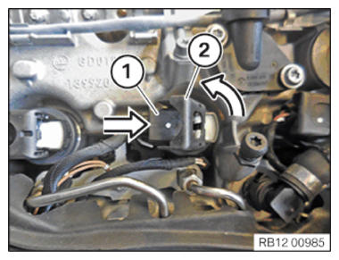
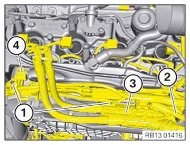
- Guide in and route the wiring harness section for the injectors of cylinders 1 to 4.NOTE: The description is for one component only. The procedure is identical for all further components.
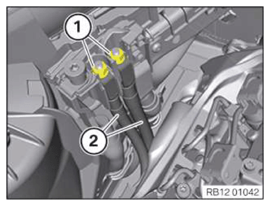
- Slide the connectors (1) of the ignition coils onto the ignition coils with the connector fastener (2) open.
- Connect the connectors (1) to the injectors. They must lock audibly.
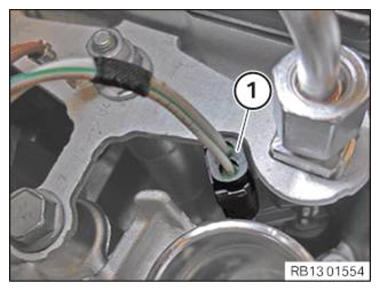
- Connect ground cable to ground pin and tighten the nuts (2).
TIGHTENING TORQUES SPECIFICATION
| Ground cable on cylinder head cover/ground pin | ||
| Nut M5 | Tightening torque | 4.6 Nm |
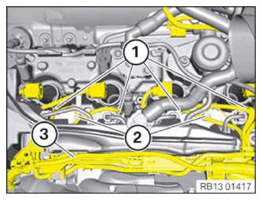
- Fasten the wiring harnesses to the wiring harness section for the injectors of cylinders 1 to 4 (3).
NOTE:
Schematic diagram is for example purposes. Some parts may differ in certain details.
- Check all connectors (1) on the injectors again to ensure they are correctly fitted.
- Check if all connectors (1) have locked.
- Connect the connector (4) to the rail pressure sensor and lock it audibly.
- Route the positive battery cables together with the cable clips (3) and secure using the ground pin.
- Tighten the ground pin.
TIGHTENING TORQUES SPECIFICATION
| Battery ground lead to cylinder head cover | ||
| Earth pin | Tightening torque | 10 Nm |
- Connect the ground cable to the ground pin and tighten the nut (2).
TIGHTENING TORQUES SPECIFICATION
| Ground cable on cylinder head cover/ground pin | ||
| Nut M5 | Tightening torque | 4.6 Nm |
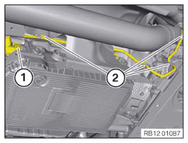
- Tighten the screws (1).
TIGHTENING TORQUES SPECIFICATION
| Cable duct to cylinder head cover/cylinder head | ||
| M6 screw | Tightening torque | 10 Nm |
- Tighten the screws (1).
TIGHTENING TORQUES SPECIFICATION
| Cable duct to cylinder head cover/cylinder head | ||
| M6 screw | Tightening torque | 10 Nm |
- Route the cables and secure to the clamps (2).
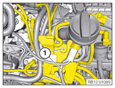
- Connect and lock the connector (1) to the transmission.
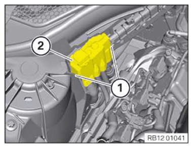
- Connect the positive battery cables (2) to the auxiliary terminal for jump starting.
- Tighten nuts (1).
TIGHTENING TORQUES SPECIFICATION
| Battery positive lead to battery positive terminal | ||
| M8 | Tightening torque | 15 Nm |
- Mount the cover (2) on the auxiliary terminal for jump starting.
- Lock the locks (1).
Follow-up work
- Refer to INSTALLING THE HOLDER FOR THE DIGITAL MOTOR ELECTRONICS CONTROL UNIT ON THE RIGHT .
- Refer to INSTALL THE INTEGRATED POWER SUPPLY MODULE (PDM) .
- Refer to INSTALLING THE DME CONTROL UNIT FOR CYLINDERS 1 TO 4 .
- Refer to INSTALLING COVER FOR THE RIGHT DME CONTROL UNIT .
- Refer to INSTALLING THE RIGHT UNFILTERED-AIR DUCT .
- Refer to INSTALLING RIGHT CLEAN AIR PIPE .
- Refer to CONNECTING THE RIGHT CHARGE AIR LINE TO THE EXHAUST TURBOCHARGER .
- Refer to INSTALLING INTAKE FILTER HOUSING .
- Refer to INSTALLING ACOUSTIC COVER .
- Refer to INSTALLING THE REAR TOP CROSS CONNECTION .
- Refer to INSTALLING FRONT CROSS CONNECTION .
- Refer to INSTALLING FRONT-END STRUT ON LEFT AND RIGHT .
- Refer to INSTALLING THE COVER ON THE LEFT AND RIGHT IN THE ENGINE COMPARTMENT AT THE TOP .
- Refer to INSTALLING REAR UNDERBODY PROTECTION .
- Refer to CONNECTING NEGATIVE BATTERY CABLE .