Top View Camera: Image Is Misaligned (SI B66 29 19)
Publication date: 2021-07-06Reference number: SI B66 29 19
TOP VIEW CAMERA: IMAGE IS MISALIGNED
SERVICE CAMPAIGN BULLETIN
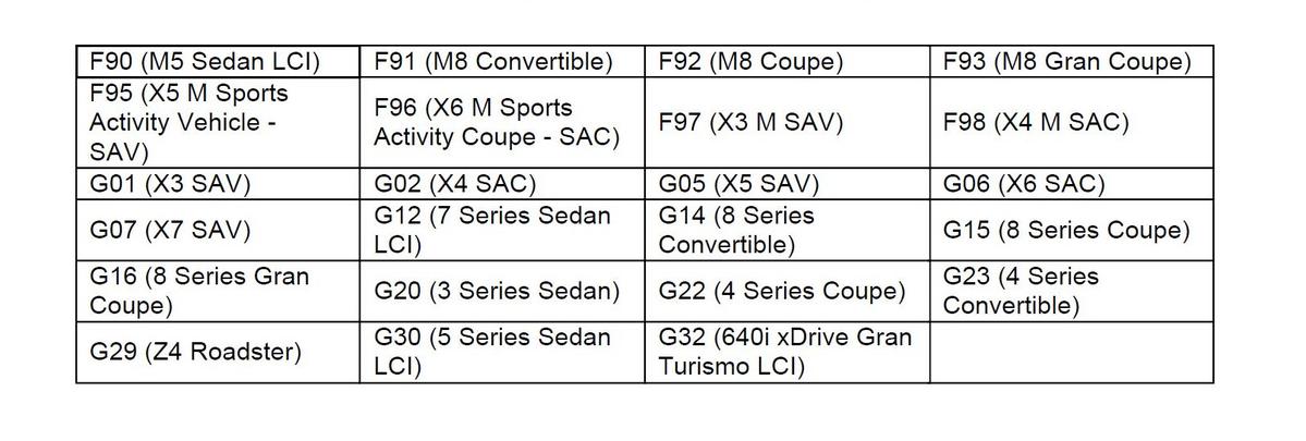
| BMW: | See The Chart Below |
SERVICE INFORMATION
This Service Information Bulletin (Revision 4) replaces SI B66 29 19 dated March 2021.
What's New (Specific text highlighted):
- Procedure - Add path to reset camera calibration test plan
MODEL
Affected vehicles are equipped with the following option code:
5DN - Parking Assistance System Plus
SITUATION
The top view image of the vehicle is misaligned when observed in the Control Information Display (CID). When the vehicle is parked in a parking spot with line markings, it is clearly noticed in the CID that the lines are not parallel to the side of the vehicle. This may be noticed on either the driver side, passenger side or both.
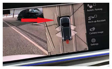
The arrow identifies the line which is shown as not parallel or straight alongside the vehicle.
CAUSE
Side view camera loose fitment in the exterior mirror bracket, causing changes to the top view image.
CORRECTION
Reposition the camera in the exterior side view mirror with felt tape and/or software update with ISTA 4.26.3x or higher. Target Integration level (I-level) of S15A/S18A-20-11-500 or higher.
PROCEDURE
Depending on the production date of the vehicle being repaired, perform the corresponding procedure outlined below.
Repair steps for G01, G02, G05, G06, G07, F97, F98 produced up to February 1, 2020 :
- Remove the left and/or right top view camera following repair instructions 66 53 060.
- Clean the area and allow area to dry.
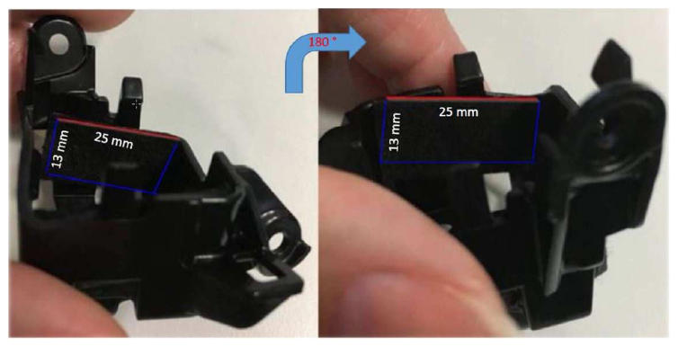
- Choose the appropriate thickness felt from the kit.
- Cut 4 pieces of felt tape approx. 13mm x 25mm x 0.7mm in size.NOTE: 2 pieces are needed per side view mirror
- Apply the felt tape to each side of the holder for the camera as indicated below.
- Reinstall the camera following the repair instructions 66 53 060.
- Fold the mirrors in and out using the button on the driver's door switch block.
- Perform the test plan to reset the camera calibration using ISTA 4.18 or higher as outlined below:
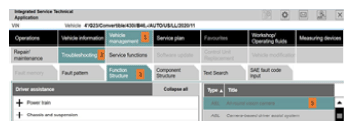
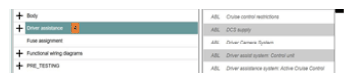
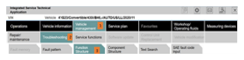
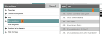
- Vehicle management/Troubleshooting/Function structure/Driver Assistance/All-round vision camera
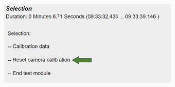
Following the numbered steps will aid in finding the test plan to reset camera data.
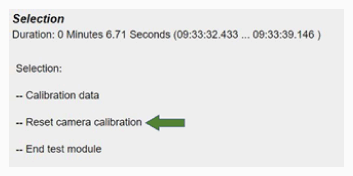
NOTE: There may be a short delay for the test plans to load after step #4.When the test plan job selections are displayed as seen in this image, select the job labeled "Reset camera calibration".
- Complete the test plan following all recommendations.
- Vehicle management/Troubleshooting/Function structure/Driver Assistance/All-round vision camera
- Drive the vehicle to recalibrate the camera - slow speed in a parking lot with minimal steering input.
- Speed under 15 mph
- Clear lane markings and/or curbs
- If possible, drive straight ahead for at least 500 yards
- Recheck the camera view to confirm issue is resolvedNOTE: Multiple drive cycles maybe needed.
- Determine the vehicle's current I-level by using either AIR or ISPA NEXT application
- If the vehicle's current I-level is lower (older) than S15A-20-11-500/S18A-20-11-500, program and code the vehicle using ISTA 4.26.3x or higher with I-level 20-11-500 or higher.
Repair steps for:
- F95, F96, F97, F98, G01, G02, G05, G06, G07 as of production date February 1, 2020
- F90, G30, G32 (LCI) as of production date July 1, 2020
- G12 (LCI) as of production date March 1, 2020
- F91, F92, F93, G14, G15, G16, G20, G22, G23, G29 as of series launch
- Fold the mirrors in and out using the button on the driver's door switch block.
- Perform the test plan to reset the camera calibration using ISTA 4.18 or higher as outlined below:
- Vehicle management/Troubleshooting/Function structure/Driver Assistance/All-round vision camera
Following the numbered steps will aid in finding the test plan to reset camera data.
NOTE: There may be a short delay for the test plans (step #5 option) to load after step #4. - Start test plan, then select continue.
When the test plan job selections are displayed as seen in this image, select the job labeled "Reset camera calibration".
- Complete the test plan following all recommendations.
- Vehicle management/Troubleshooting/Function structure/Driver Assistance/All-round vision camera
- Drive the vehicle to recalibrate the camera - slow speed in a parking lot with minimal steering input.
- Speed under 15 mph
- Clear lane markings and/or curbs
- Drive straight ahead for at least 500 yards
- Recheck the camera view to confirm issue is resolvedNOTE: Multiple drive cycles maybe needed
- Determine the vehicle's current I-level by using either AIR or ISPA NEXT application.
- If the vehicle's current I-level is lower (older) than S15A-20-11-500/S18A-20-11-500, program and code the vehicle using ISTA 4.26.3x or higher with I-level 20-11-500 or higher.NOTE: ISTA 4.26.3x is expected to be released on November 24.
- Reassess the vehicle.
Always connect a BMW-approved battery charger/power supply ( SI B04 23 10 ) when performing programming.
For information on programming and coding with ISTA, refer to CenterNet/TIS/Technical Documentation/Programming and Diagnostics/Programming Documentation.
PARTS INFORMATION
| Part Number | Description | Quantity |
|---|---|---|
| 51 45 2 353 024 | Set felt strip self-adhesive | Sublet as needed |
WARRANTY INFORMATION
During this workshop visit, the affected vehicle may also show one or more programming and encoding Technical Campaign repairs open, the programming and encoding procedure may only be invoiced one time.
If you have this open campaign situation and on a vehicle that also needs to have its exterior side view mirror camera(s) repositioned, after performing the repositioning repair procedure:
Update the vehicle to the current available I-level by performing and submitting for one of the open Technical Campaigns instead.
Please be sure to also perform any additional work (before and after) the campaign repairs require and/or close the remaining open programming and encoding Technical Campaign repairs as outlined in the corresponding Service Information Bulletin.
Based on the above, the exterior side view mirror camera repositioning repair procedure below that applies is covered under the terms of the BMW New Vehicle Limited Warranty for Passenger Cars and Light Trucks.
| Defect Code: | 6653064000 | Surround view camera, TRVC (Top View camera) in outside rearview mirror poorly adjusted/outside of tolerance |
Repair performed in conjunction with performing a programming and encoding Technical Campaign repair(s) on the vehicle
| Labor Operation | Description | Labor Allowance |
|---|---|---|
| 66 53 560 | Removing and installing left or right top view camera | Refer to AIR |
| Or: | ||
| 66 53 561 | Removing and installing both top view cameras | Refer to AIR |
| Or, the: | ||
| Repair is performed on a vehicle with no open programming and encoding Technical Campaign repair(s) | ||
| Labor Operation | Description | Labor Allowance |
| 00 00 006 | Performing vehicle test (with vehicle diagnosis system - checking faults) (Main work) | Refer to AIR |
| Or: | ||
| 00 00 556 | Performing vehicle test (with vehicle diagnosis system - checking faults) (Plus work) | Refer to AIR |
| And: | ||
| 61 21 528 | Connect an approved battery charger/power supply (indicated in AIR as Charging battery) | Refer to AIR |
| And: | ||
| 66 53 560 | Removing and installing left or right top view camera | Refer to AIR |
| Or: | ||
| 66 53 561 | Removing and installing both top view cameras | Refer to AIR |
| And | ||
| 61 00 730 | Programming/encoding control unit(s) | Refer to AIR |
If you are using a Main labor code for another repair, use the Plus code labor operation 00 00 556 instead of 00 00 006.
Refer to AIR for the corresponding flat rate unit (FRU) allowances.
And, as needed:
Sublet - Bulk Materials (RO and Claim Comments Required)
| Sublet Code 4 | See the sublet reimbursement calculations below | Reimbursement for the repair-related bulk materials (Do not use the BMW part number for claim submission) |
Sublet reimbursement calculation for claiming the applicable repair-related bulk materials (BMW part number) is at the dealer net price amount for the quantity used plus your center's handling.
Enter this material cost in sublet and itemize the amount on the repair order and in claim comment section.
Programming and Encoding - Vehicle Control Units (RO and Claim Comments Required)
The programming procedure automatically reprograms and encodes all vehicle control modules which do not have the latest software I-level. If one or more control module failures occur during this programming procedure:
- Please claim this consequential control module-related repair work (including the primary IRAP Control Unit Recovery procedure as required, refer to the SIR in AIR) under the defect code listed in this bulletin with the applicable AIR labor operations.
Please explain this additional work (The why and what) on the repair order and in the claim comments section
For control module failures that occurred prior to performing this programming procedure:
- When covered under an applicable limited warranty, claim the applicable test plan and the corresponding control module-related repair work using the applicable defect code and labor operations in AIR (including diagnosis with separate punch times).
As applicable to your center, please refer to SI B01 01 20 or B01 07 20 for claiming your diagnosis work time, job/repair work time (WT), WT and the repair-related explanation procedures.
QUESTIONS REGARDING THIS BULLETIN
| Technical inquiries | Submit feedback at the top of this bulletin |
|---|---|
| Warranty inquiries | Submit an IDS ticket to the Warranty Department or use the chat available in the Warranty Documentation Portal |
| Parts inquiries | Submit an IDS ticket to the Parts Department |