Installing the lane change warning sensor at the front
NOTE:
TECHNICAL INFORMATION
Latch mechanisms, guides and mounting elements must not be damaged or missing.
Latch mechanisms, guides and mounting elements must not be damaged or missing.
NOTE:
Description is for left component only. Procedure on the right side is identical.
NOTE:
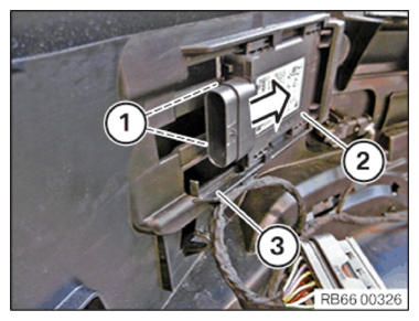
To provide a better overview:
Schematic diagram with partially hidden components.
- Slide lane change warning sensor (2) in the direction of the arrow into holder (3) up to the limit position.
- Lock the lock (1).
- Ensure that the lock (1) is locked correctly.
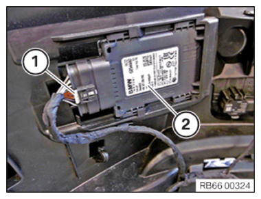
- Connect the connector (1) to the sensor (2) and lock it.
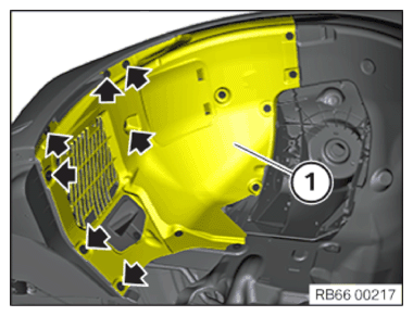
- Correctly position the wheel arch trim panel (1).
- Tighten all bolts (arrows).
TIGHTENING TORQUES SPECIFICATION
| Wheel arch cover | ||
| Screw | Tightening torque | 3 Nm |
| Plastic nut | Tightening torque | 2.6 Nm |