Install injectors
NOTE:
TECHNICAL INFORMATION
When assembling, it is essential to observe screwing sequences and tightening torques.
Failure to comply with the regulations can lead to leaks and damage.
When assembling, it is essential to observe screwing sequences and tightening torques.
Failure to comply with the regulations can lead to leaks and damage.
- Insert injectors in injector bores.
- Position special tool (1) 2 410 777 on the injector shaft.
- Screw in the screws (2) in the injector shaft by a few threads.
- Screw in the extraction thread (4) until the threaded sleeves (3) can be screwed onto the injectors.
- Screw on and tighten the threaded sleeves (3) onto the injectors.
- Tighten down screws (2).TIGHTENING TORQUES SPECIFICATION
Special tool 2 410 777 to injector well M6 Tightening torque 8 Nm - Adjust the torque wrench (1) to 2 Nm, anti-clockwise.
- Position the torque wrench (1) and special tool (2) 0 490 507 (00 9 170) on the hexagon head of special tool 2 410 777 .
- Turn the torque wrench (1) in anti-clockwise direction until 2 Nm apply.
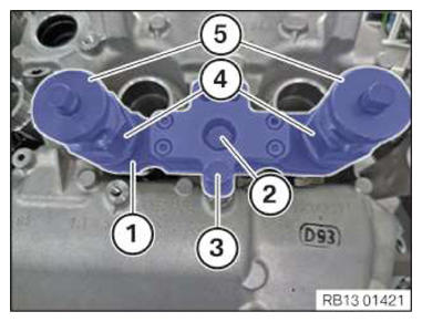
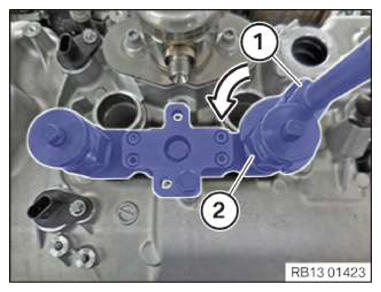
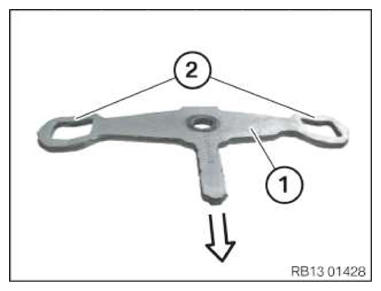
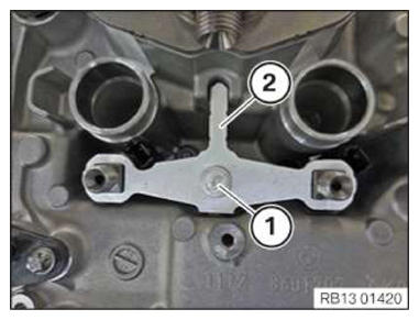
- Install hold-down device (1) with curvatures (see arrow) downwards.
- Install the hold-down device (2) on the injectors.
- Screw in the screw (1) by a few turns only.NOTE: TECHNICAL INFORMATION
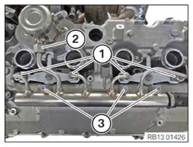
Always install the high pressure line or rail free of distortion. To ensure distortion-free installation of the high pressure line and to avoid damaging the thread, it must be possible for both nuts to be screwed on to the injectors easily hand force.NOTE: Description is for left component only. Procedure on the right side is identical. - First insert the high-pressure rail at the high-pressure pump connection, then lower to the point where the ball heads are positioned inside the injector connections and the high-pressure rail is correctly positioned.
- Then tighten the nuts (1) on the injectors so they are hand-tight.
- Next, hand-tighten the nut (2) of the high pressure pump.
- Lastly, mount screws (3) and hand-tighten.
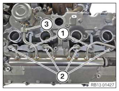
- Tighten down screws (3).TIGHTENING TORQUES SPECIFICATION
Rail on cylinder head cover M6x25 Tightening torque 10 Nm - Tighten the screws (1) the hold-down device.TIGHTENING TORQUES SPECIFICATION
Hold-down device to cylinder head M7 Tightening torque 13 Nm - Tighten the nuts (2) on the injectors.TIGHTENING TORQUES SPECIFICATION
Rail to injector M12 Joining torque 10 Nm Tightening torque 23 Nm - Tighten nut (3) on the high pressure pump.
TIGHTENING TORQUES SPECIFICATION
| Rail to high pressure pump | ||
| M14 | Joining torque | 10 Nm |
| Tightening torque | 30 Nm | |
Follow-up work
- Refer to INSTALLING SOUND INSULATION ON THE LEFT CYLINDER HEAD COVER .
- Refer to INSTALLING THE SOUND INSULATION ON THE RIGHT-HAND CYLINDER HEAD COVER .
- Refer to SECURE THE WIRING HARNESS ON THE CYLINDER HEAD COVER ON THE RIGHT .
- Refer to MOUNT THE WIRING HARNESS ON THE CYLINDER HEAD COVER ON THE LEFT .
- Refer to INSTALLING THE HOLDER FOR THE DIGITAL MOTOR ELECTRONICS CONTROL UNIT ON THE RIGHT .
- Refer to INSTALL THE INTEGRATED POWER SUPPLY MODULE (PDM) .
- Refer to INSTALLING THE DME CONTROL UNIT FOR CYLINDERS 1 TO 4 .
- Refer to CHECK THE COOLANT LEVEL IN THE LOW-TEMPERATURE COOLANT CIRCUIT AND TOP UP, IF NEEDED .
- Refer to INSTALL REAR UNDERBODY PROTECTION .
- Refer to INSTALLING THE LEFT UNFILTERED-AIR DUCT .
- Refer to INSTALLING THE RIGHT UNFILTERED-AIR DUCT .
- Refer to INSTALL LEFT CLEAN AIR PIPE .
- Refer to INSTALL RIGHT CLEAN AIR PIPE .
- Refer to CONNECTING THE RIGHT CHARGE AIR LINE TO THE EXHAUST TURBOCHARGER
- Refer to CONNECTING THE LEFT CHARGE AIR LINE TO THE EXHAUST TURBOCHARGER
- Refer to INSTALLING THE IGNITION COILS .
- Refer to INSTALLING INTAKE FILTER HOUSING .
- Refer to INSTALL ACOUSTIC COVER .
- Refer to INSTALL THE REAR TOP CROSS CONNECTION .
- Refer to INSTALL FRONT CROSS CONNECTION .
- Refer to INSTALLING FRONT-END STRUT ON LEFT AND RIGHT .
- Refer to INSTALLING THE COVER ON THE LEFT AND RIGHT IN THE ENGINE COMPARTMENT AT THE TOP
- Refer to DISCONNECTING ALL BATTERY GROUND LEADS .
- Refer to RESET ULTRA-SMALL QUANTITY ADAPTATION .