Installing the right high-pressure rail
NOTE:
TECHNICAL INFORMATION
When assembling, it is essential to observe screwing sequences and tightening torques.
Failure to comply with the regulations can lead to leaks and damage.
When assembling, it is essential to observe screwing sequences and tightening torques.
Failure to comply with the regulations can lead to leaks and damage.
NOTE:
The description is for one component only. The procedure is identical for all further components.
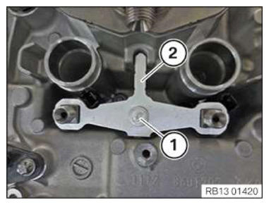
- Loosen screws (1).
- Slacken hold-down device (2).NOTE: TECHNICAL INFORMATION
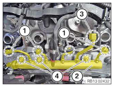
Always install the high pressure line or rail free of distortion. To ensure distortion-free installation of the high pressure line and to avoid damaging the thread, it must be possible for both nuts to be screwed on to the injectors easily hand force. - First insert the rail (2) at the high pressure pump connector, then lower it to the point where the ball heads are positioned inside the injector connections and the rail is correctly positioned.
- Then tighten the nuts (1) on the injectors so they are hand-tight.
- Next, hand-tighten the nut (3) of the high pressure pump.
- Lastly, mount screws (4) and hand-tighten.
- Tighten down screws (4).TIGHTENING TORQUES SPECIFICATION
Rail to cylinder head cover M6x25 screw Tightening torque 10 Nm NOTE: The description is for one component only. The procedure is identical for all further components. - Tighten down screws (1).TIGHTENING TORQUES SPECIFICATION
Hold-down device to cylinder head cover screw Tightening torque 13 Nm - Tighten nuts (1) on the injectors with the special tool 0 495 908 (371 150)
.TIGHTENING TORQUES SPECIFICATION
High-pressure rail to injectors Nuts Tightening torque 23 Nm - Tighten nut (3) on the high pressure pump with the special tool 0 491 277 (13 5 020)
.TIGHTENING TORQUES SPECIFICATION
Fuel supply line/rail to high pressure pump Nut Tightening torque 30 Nm - Tighten down screws (4).TIGHTENING TORQUES SPECIFICATION
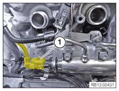
Rail to cylinder head cover M6x25 screw Tightening torque 10 Nm - Connect plug connection (1) and lock.
Follow-up work
- Refer to INSTALL IGNITION COILS OF CYLINDER BANK 1 .
- Refer to INSTALLING CONTROL UNIT HOLDER FOR CYLINDERS 1 TO 4 .
- Refer to INSTALLING THE COVER OF THE RIGHT DME CONTROL UNIT .
- Refer to DISCONNECTING ALL BATTERY GROUND LEADS .