Installing the engine wiring harness for the sensor system 2
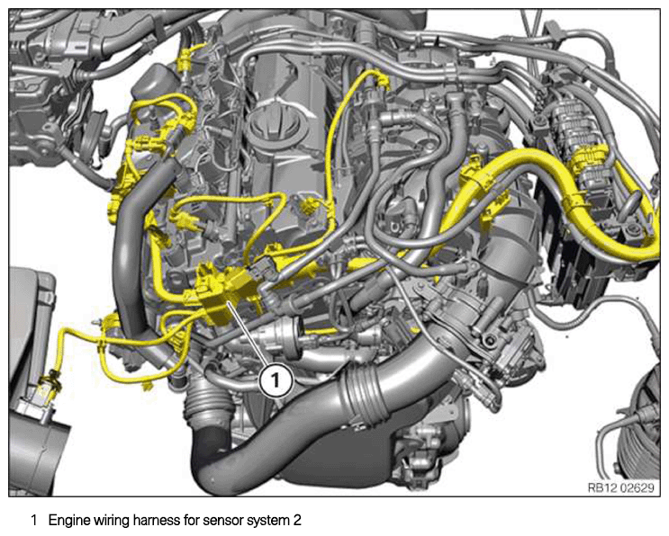
Engine wiring harness for sensor system 2
NOTE:
RISK OF DAMAGE
Improper routing of cables and wiring harnesses.
Trapped, crushed or damaged cables may cause short circuits and malfunctions.
Improper routing of cables and wiring harnesses.
Trapped, crushed or damaged cables may cause short circuits and malfunctions.
- Route all cables without abrasions, do not trap and crush.
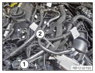
- Guide in and install the engine wiring harness (1) for sensor system 2.
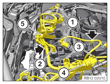
- Feed in and install the wiring harness section (5) for sensor system 2.
- Connect connectors (4) and lock.
The connector (4) must engage audibly.
- Install and lock the locking mechanisms (3).
- Secure the clamps (arrows).
- Connect connectors (2) and lock.
The connectors (2) must engage audibly.
- Connect connectors (1) and lock.
The connectors (1) must engage audibly.
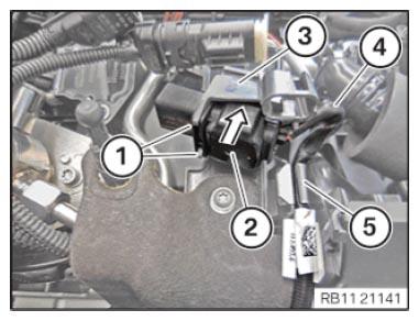
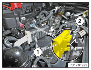
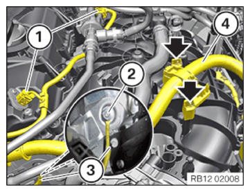
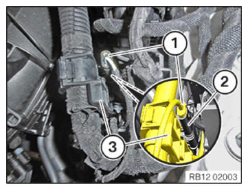
- Guide in connector (2) in direction of arrow to the carrier plate (3) and install.
- Ensure the locking mechanisms (1) engage correctly.
- Secure cable (4) to the clamp (5).
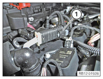
- Connect connectors (1) and lock.
- Make sure the connector (1) engages audibly.
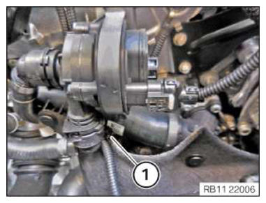
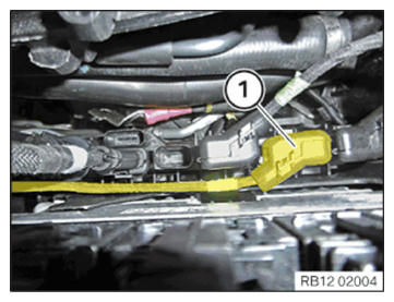
- Connect the connector (1) with the holder (2) and lock (arrow).
The connector (1) must engage audibly.
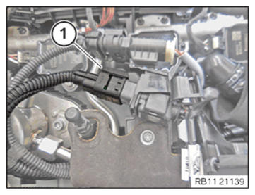
- Connect connectors (1) and lock.
The connector (1) must engage audibly.
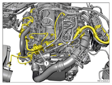
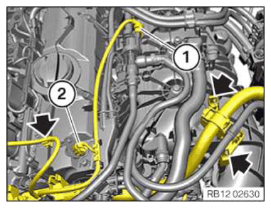
- Guide in and install the engine wiring harness (2) for sensor system 2.
- Secure the clamps (arrows).
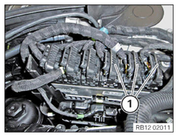
- Connect connectors (1) and lock.
The connectors (1) must engage audibly.
- Secure clamps (1).
- Version 1:
Feed in and install the wiring harness section (4) for sensor system 2.
- Ensure that the locking mechanisms (arrows) engage correctly.
- Thread in ground cable (3) and install.
- Tighten the nut (2).
TIGHTENING TORQUES SPECIFICATION
| Standard screw connection M6 | ||
|---|---|---|
| M6 | Tightening torque | 8 Nm |
- Connect connectors (1) and lock.
The connectors (1) must engage audibly.
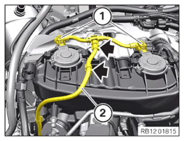
- Version 2:
Feed in and install the wiring harness section (4) for sensor system 2.
- Ensure that the locks and the clamps (arrows) engage correctly.
- Attach connector (1) to the tank vent valve and lock it audibly.
- Attach connector (2) to the intake camshaft sensor and lock it audibly.
- Feed in and install the wiring harness section (2) for sensor system 2.
- Lock holder (1).
- Feed in and install coolant line (2).
- Lock holder (1).
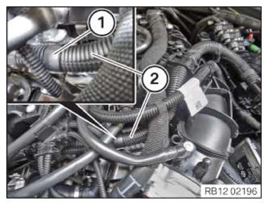
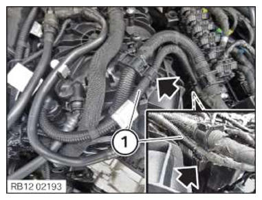
- Guide in and lock the wiring harness section (1) for sensor system 2 in the bracket (arrows).
- Connect connectors (1) and lock.
The connector (1) must engage audibly.
- Attach the connector (2) to the holder (3) and lock.
The connector (2) must engage audibly.
- Connect connectors (1) and lock.
The connector (1) must engage audibly.
- Connect connectors (1) and lock.
The connectors (1) must engage audibly.
Follow-up work
- Refer to INSTALLING COVER FOR THE DME CONTROL UNIT .
- Refer to INSTALLING THE CYLINDER HEAD COVER ACOUSTIC COVER .
- Refer to INSTALLING DIFFERENTIAL PRESSURE SENSOR .
- Refer to INSTALLING ENGINE VENTILATION LINE .
- Refer to INSTALLING THE ACOUSTIC COVER FOR THE ENGINE AT THE FRONT .
- Refer to INSTALLING CHARGE AIR LINE .
- Refer to INSTALLING RESONATOR .
- Refer to INSTALLING INTAKE SILENCER HOUSING .
- Refer to INSTALLING ACOUSTIC COVER AT REAR .
- Refer to FASTENING HIGH-VOLTAGE CABLES ON THE ELECTRICAL MACHINE ELECTRONICS .
- Refer to INSTALLING THE CENTER COWL UPPER PART .
- Refer to INSTALLING TENSION STRUT ON SHOCK TOWER .
- Refer to INSTALLING WINDSHIELD PANEL COVER .
- Refer to INSTALLING LEFT AND RIGHT WIPER ARM .
- Refer to INSTALLING THE REAR RIGHT ENGINE COMPARTMENT COVER .
- Refer to INSTALLING THE COVER OF THE ENGINE COMPARTMENT ON THE REAR LEFT .
- Refer to INSTALLING THE FRONT HOOD SEAL AT THE REAR .
- Refer to INSTALLING ACOUSTIC COVER .
- Refer to TAKING HOOD OUT OF THE SERVICE POSITION .
- Refer to CONNECTING NEGATIVE BATTERY CABLE .