Install the stiffening plate
- Feed in the thrust field (3) at the lines.
- Position the thrust field (3) on the front subframe with a support person and fold down the front a little.
- Position the bracket with the clip (2) on the thrust field (3).
- Install the expanding rivet (1) from the top.
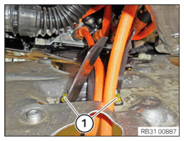
- Tighten nuts (1).TIGHTENING TORQUES SPECIFICATION
Thrust field to holder Plastic nut tightening torque 2.6 Nm - Position the thrust field on the front axle support.
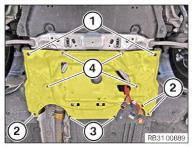
- Replace screws (4).
Parts: Screws
- Tighten down screws (4).TIGHTENING TORQUES SPECIFICATION
Thrust field to front axle support M6
Replace screws.Tightening torque 8.8 Nm - Tighten down screws (3).TIGHTENING TORQUES SPECIFICATION
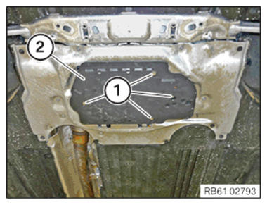
Underbody protection screw Tightening torque 3 Nm - Tighten down screws (2).TIGHTENING TORQUES SPECIFICATION
Wheel arch cover screw 3 Nm Plastic nut 2.6 Nm - Tighten down screws (1).TIGHTENING TORQUES SPECIFICATION
Cover, steering unit screw Tightening torque 3 Nm Installing the Car Pad Module (CPM)
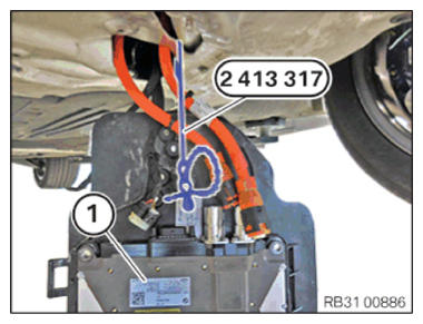
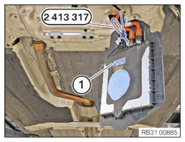
NOTE: Schematic diagram is for example purposes. Some parts may differ in certain details. - Tie up the Car Pad Module (CPM) (1) with the special tool 2 413 317
.
Do not leave the Car Pad Module (CPM) (1) suspended from the lines!
NOTE: DANGER
Potential equalization in high-voltage system.
Mortal hazard if the potential equalization screw connection is not correct!- Observe the safety requirements for the potential equalization screw connection.
- Clean contact faces and have then checked by a second person.
- Tighten the screws/nuts for potential equalization with torque; have a second person check the torque.
- Correct execution of these tasks must be documented in the vehicle records by both persons.
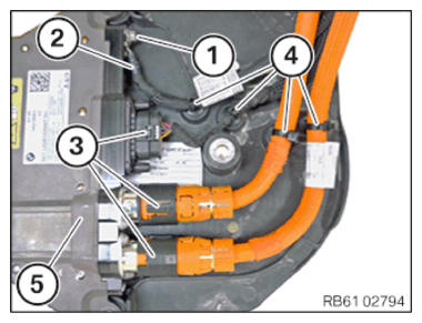
- Position the potential equalization (2) on the Car Pad Module (CPM) (5).
- Tighten down screw (1).TIGHTENING TORQUES SPECIFICATION
Potential equalization to Car Pad Module (CPM) M6x16 screw tightening torque 8 Nm - Connect connectors (3) and lock.
- Replace the clips with the cable tie (4).
Parts: Clips with cable tie
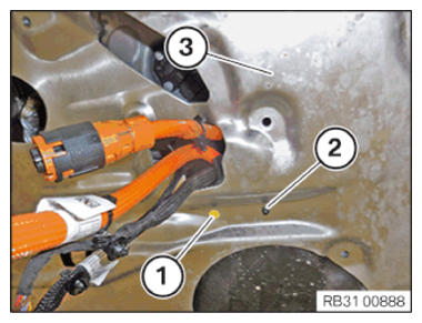
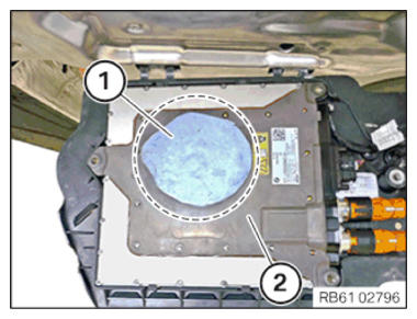
- Mark the installation position of the adhesive pad (1) on the Car Pad Module (CPM) (2).
- Release the adhesive pad (1).
- Replace the adhesive pad (1).
Parts: Adhesive pad
- Fasten the adhesive pad (1) according to the mark made on the Car Pad Module (CPM) (2).
- Release the special tool 2 413 317
.
Do not leave the Car Pad Module (CPM) (1) suspended from the lines!
- Attach the lid (2) with the Car Pad Module (CPM) on both guides on the thrust field and fold upwards.
- Tighten down screws (1).TIGHTENING TORQUES SPECIFICATION
Lid to thrust field M8x22 screw tightening torque 28 Nm
Follow-up work
- Refer to DISCONNECTING ALL BATTERY GROUND LEADS .