Install Engine Mount In Front Of Cowling With Wheel Arch
Further information is available.
- Pre-clean bonding surfaces on vehicle and on new part with cleaning agent R2.CONSUMABLE - CLEANING AGENT DESCRIPTION (R2)
Cleaning agent R2 500 ml 83190417324 - Clean bonding surfaces on vehicle and on new part with cleaning agent R1.CONSUMABLE - CLEANING AGENT DESCRIPTION (R1)
Cleaning agent R1 100 ml, Bottle 83192211217 - Apply adhesive K1 to the bonding surfaces.ADHESIVE DESCRIPTION
Body adhesive K1 195 ml 83190413015 - Install the new parts with an alignment bracket or a universal mount.
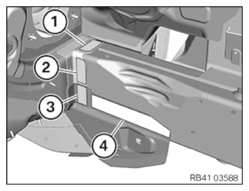
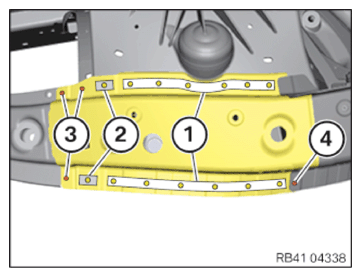
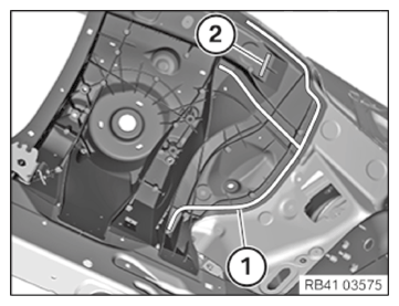
- Rivet new parts in the areas (1), (2) and (4) with blind rivets N1.CONSUMABLE - BLIND RIVET DESCRIPTION (N1)
Blind rivet N1
Ø 6.5 mm; clamping area 2.8-4.8 mm83190301414 - In the area (3), use a bind rivet N2.CONSUMABLE - BLIND RIVET DESCRIPTION (N2)
Blind rivet N2
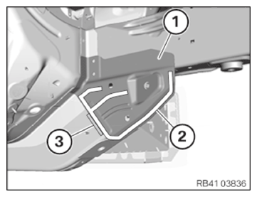
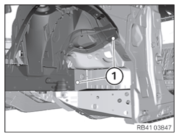
Ø 6.5 mm; clamping area 4.8-6.8 mm83190301419 - Weld reinforcement (1) in the area (2).
- In the (3), MAG weld analogue to the series.
- Weld reinforcement (1) in the area (2).
Avoid excessive application of heat in this process.
The cowling cross-member (3) is filled with hardly inflammable cavity foam.
- In case of smoke formation: Stop the welding procedure and cool the welded area with compressed air if applicable.
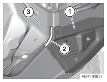
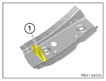
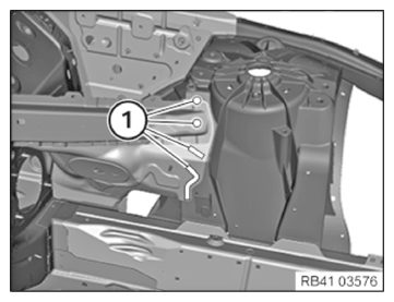
- Rivet new parts in the areas (1) with blind rivets N1.CONSUMABLE - BLIND RIVET DESCRIPTION (N1)
Blind rivet N1
Ø 6.5 mm; clamping area 2.8-4.8 mm83190301414
NOTE:
TECHNICAL INFORMATION
For additional information see: 41 00... Installation of a cavity sealing (not expanding)
For additional information see: 41 00... Installation of a cavity sealing (not expanding)
- Apply sealant D1 to the new cavity sealing (1).CONSUMABLE - SEALANT DESCRIPTION
Sealant D1 (seam sealing) 310 ml 83422409985 - Install cavity sealing (1) in the new part.
- Apply sealant D1 to cavity sealing (1).
- Install the carrier support for the new part.
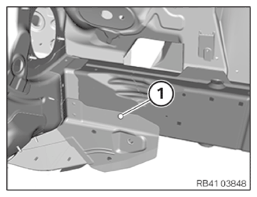
- Rivet the new parts in the areas (1) and (2) with blind rivets N1.CONSUMABLE - BLIND RIVET DESCRIPTION
Blind rivet N1
Ø 6.5 mm; clamping area 2.8-4.8 mm83190301414 - Rivet the new parts in the areas (3) with blind rivets N3.CONSUMABLE - BLIND RIVET DESCRIPTION (N3)
Blind rivet N3
Ø 4 mm; clamping area 1-3 mm83190301421 - In the area (4), use a bind rivet N6.CONSUMABLE - BLIND RIVET DESCRIPTION (N6)
Blind rivet N6
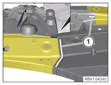
Ø 4 mm; clamping area 3-5 mm83192158655 - Weld the new parts in areas (1) according to the new part preparation process.
Avoid excessive application of heat to adhesive areas.
- Weld the new part in areas (1) according to the new part preparation process.
Avoid excessive application of heat to adhesive areas.
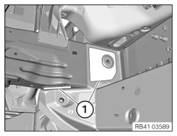
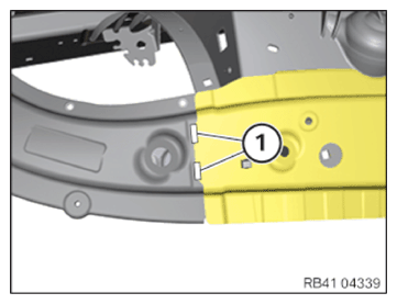
- Rivet new parts in the areas (1) and (2) with blind rivets N1.CONSUMABLE - BLIND RIVET DESCRIPTION
Blind rivet N1
Ø 6.5 mm; clamping area 2.8-4.8 mm83190301414 - Rivet the new part in the areas (1) with blind rivet N1.CONSUMABLE - BLIND RIVET DESCRIPTION
Blind rivet N1
Ø 6.5 mm; clamping area 2.8-4.8 mm83190301414 Installing the EMC screw
- Drill the hole with a diameter of 4.2 mm after the adhesive completely hardens.
- Screw in the EMC screw.
- Seal the EMC screw with the sealant.CONSUMABLE - SEALANT DESCRIPTION
Sealant D1 (seam sealing) 310ml 83422409985 - Install two EMC screws in the areas (1).CONSUMABLE - SCREW DESCRIPTION
screw
EMC screw, SF Plus, M5x1583190301639 - Install an EMC screw in area (1).CONSUMABLE - SCREW DESCRIPTION
screw
EMC screw, SF Plus, M5x1583190301639
Follow-up work
- Refer to CUT THE THREADS .
- Refer to ACTIVATE HIGH-VOLTAGE SYSTEM .
- Refer to INSTALL FLAP IN RIGHT LUGGAGE COMPARTMENT TRIM PANEL .