Prepare New Part
Further information is available.
TECHNICAL INFORMATION
Structural adhesive bonding.
Observe preparation of bonding surfaces.
For additional information see: BMW/MINI BONDING INSTRUCTIONS (530i 2017-2022, 530i xDrive 2017-2022, 530e PHEV 2018-2022, 530e xDrive PHEV 2018-2022, 540i 2017-2022, 540i xDrive 2017-2022, M550i xDrive 2018-2022) .
NOTE:
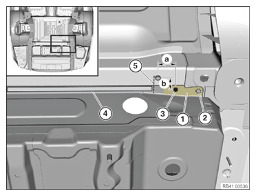
Perform the steps on the left and right side.
- Adjust the new parts in combination with the tail panel to fit and secure.
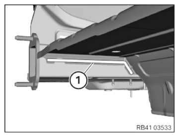
- Prepare area (1) for structural adhesive bonding of steel to steel and aluminum.
- Transfer the position of the hole (2) that resulted from the removal on the vehicle to the new part. Set hole (2) ø 6.8 mm for blind rivet.
- Set the new hole (3) ø 6.8 mm according to the specified dimensions.
Dimension a = 40 mm from hole 012 mm.
Dimension b = 24 mm from hole 012 mm.
- Prepare area (4) from the reference line (5) for joining by welding.
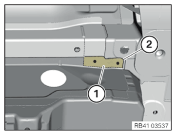
- Mark the area (1) for a future adhesive application on the vehicle and on the new part (2).
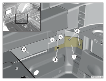
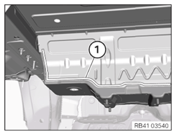
- Prepare area (1) for structural adhesive bonding of steel to steel and aluminum.
- Assign the positions of the holes already present in area (2) of the vehicle to the new part. Set holes (2) ø 6.8 mm for blind rivet.
- Set hole (3) ø 6.8 mm according to dimension b. Dimension b = 30 mm from component edge.
- Prepare area (4) according to dimension a for joining by welding. Dimension a = 40 mm.
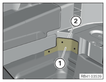
- Mark the area (1) for a future adhesive application on the vehicle and on the new part (2).
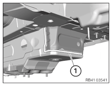
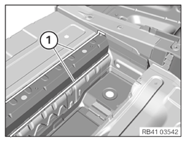
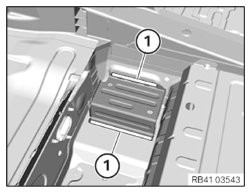
- Prepare areas (1) for joining by welding.
- Prepare areas (1) for joining by welding.
- Prepare areas (1) for joining by welding.
- Prepare areas (1) for joining by welding.
- Prepare areas (1) for joining by welding.
- Remove new part and deburr holes.
- Remove adhesive residue from the bonded connections of the series from the vehicle.
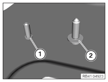
Replace coarse thread studs and threaded welding studs, steel surface
NOTE: Schematic diagram is for example purposes. Some parts may differ in certain details. - Refer to the number and position of the component to be replaced or the attachments.
- Replace coarse thread bolt (1) and threaded welding bolt (2).
Parts: Coarse Thread Bolt (1), Threaded Weld Bolt (2)
- Weld the coarse threaded bolt (1) and threaded welding bolt (2) onto the new part.
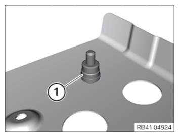
Check ground pins and replace if necessary
NOTE: Schematic diagram is for example purposes. Some parts may differ in certain details. - Check the ground pins (1) for stability and replace if necessary.