Engine Replacement And Engine Repairs (SI B11 09 15)
Publication date: 2025-01-30Reference number: SI B11 09 15
Supersedes refnos: SI B11 02 20
ENGINE REPLACEMENT AND ENGINE REPAIRS
SERVICE CAMPAIGN BULLETIN
| BMW: | All Models |
SERVICE INFORMATION
This Service Information Bulletin (Revision 8) replaces SI B11 02 20 dated June 2024.
What's New :
- Procedure: Engine oil color information
- Procedure: Cooling system contamination (engine oil or transmission fluid) information
INFORMATION
New and remanufactured replacement engine assemblies are NOT pre-filled with engine oil.
After replacing an engine with a new or remanufactured engine assembly, the engine oil level must be verified as outlined in the procedure below first, before starting the engine for the first time.
If the new or remanufactured replacement engine is started to determine electronically if the engine is filled with the appropriate amount of engine oil, damage to the replacement engine can occur immediately.
The engine may have some residual engine oil from assembly, but this is not enough engine oil to properly lubricate the engine to measure the engine oil level electronically when it is started for the first time.
Furthermore, the electronic engine oil measurement is only operational when the engine is running at its full operating temperature. Checking the engine oil without the engine running at operating temperature will lead to an incorrect or incomplete measurement.
After replacing the engine or making engine repairs that require the replacement or removal of the following components, you must perform a short oil pump and oil supply circuit priming procedure. Refer to the appropriate section below.
- Engine bearings
- Camshafts
- Bed plate resealing
- Engine oil pump
- Engine oil filter housing
- Cylinder head
- Engine oil cooler, oil cooler supply line and oil cooler return lines
The VANOS gears do not require engine oil circuit priming.
Reusing or transferring components from the old engine to the new engine:
Always inspect and clean prior, as needed, when reusing or transferring components.
If required, use a borescope to look inside the components. Contaminated engine parts (metal particles, fuel, water, antifreeze, etc.) can lead to subsequent engine or component failure and will not be covered by Warranty.
If the engine is hydrolocked due to water ingestion, clean the entire intake track by removing all of the induction system components from the vehicle and ensuring no water is present before starting the replacement engine.
If the engine is hydrolocked due to a leaking injector, clean the entire intake track by removing all of the induction system components from the vehicle and ensuring no fuel is present before starting the replacement engine. Replace the affected injector.
If the engine failure includes damage to the pistons and valves, for example, a hole in the piston or a broken valve then inspect and clean the intake track and the exhaust system by removing and reinstalling all of the components for inspection before starting the replacement engine.
If the lubrication circuit is contaminated with metal fragments, then the oil cooler and the oil cooler lines need to be replaced. Cleaning these components will not be effective.
If necessary, always use a borescope to inspect all of parts if the component cannot be inspected visually, for example, an induction pipe with multiple direction changes and blind spots.
If repairing the engine always account for all the broken parts, timing chain guides, fasteners, rings etc., using a borescope in the oil drain plug hole or if necessary, the oil pan may need to be removed if all of the parts are not accounted for.
All vehicles using two turbos and vacuum-operated wastegates:
When disassembling the vacuum supply system, always ensure the hoses and components are marked or labeled so that reassembly is performed correctly. Always refer to the applicable repair instruction to ensure the vacuum hoses are connected to the correct bank turbocharger wastegate actuator or EPDW.
If the hoses are not connected correctly subsequent internal engine piston and combustion chamber damage can occur. Engine or component failure related to incorrectly connected vacuum hoses will not be covered by Warranty.
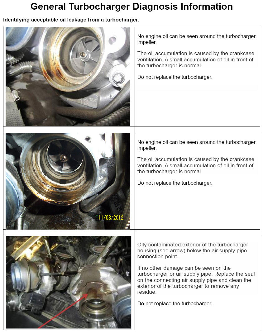
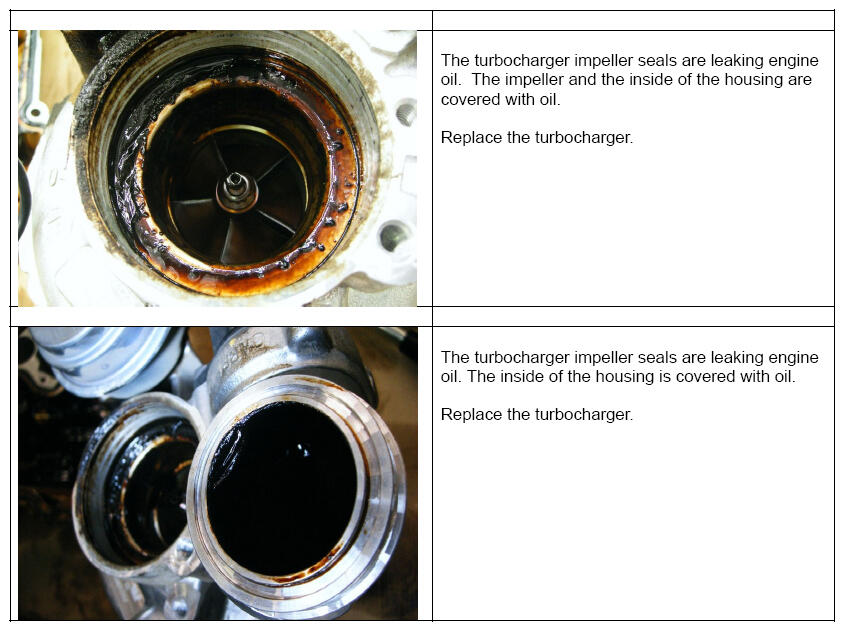
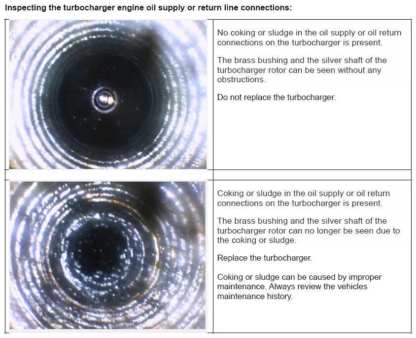
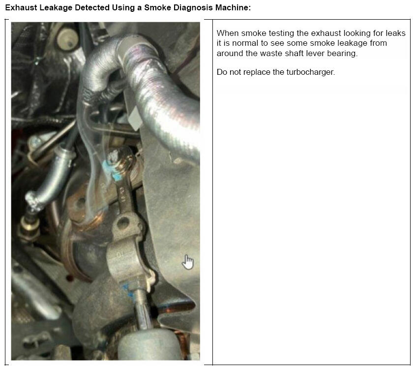
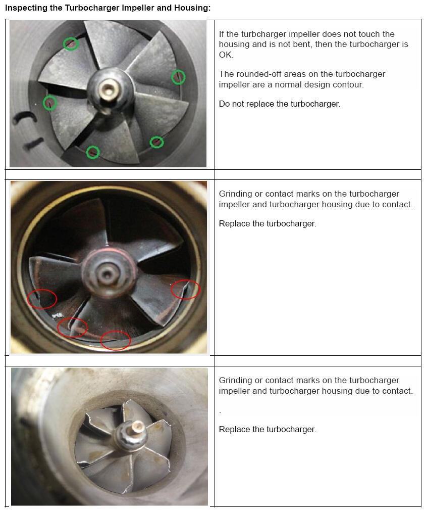
General Turbocharger Diagnosis Information:
Refer to the attached document for general turbocharger diagnosis information.
Cold climate engine replacements and engine repairs:
Installing parts that have been subjected to deep freeze conditions while being shipped from the parts warehouse or stored at your dealer require some time to adjust to the workshop environment.
- During the winter months you must allow the hardware to be within 20 degrees of room temperature before assembling components
- Installing parts that are not within this temperature range can affect gasket sealing surfaces and the tightening torque of the fasteners
Installing replacement engines that are not warmed may not be ready to accept the fasteners for the transmission bellhousing, flywheel bolts, belt driven accessories, etc. These fasteners may loosen over time, or the materials may fail if not torqued to specification at a reasonable temperature.
Glues and sealers way not cure correctly under these colder conditions. This may result in premature component failure or leaks.
Components such as cylinder heads and engines may need a full 24 hours to warm before installations can be started. These are dense components and require extra time.
- We recommend the cartons are opened during this warming period
- Some of the cartons and packing materials can insulate so well that the parts may not warm up with them closed and sealed
PROCEDURE
Vehicles equipped with the following engine families:
N20, N26, N55, N63, N63T, N63R, N63B, N63M, S55, S63, S63T, S63M, B36, B38, B46, B48, B58, S58 and S68
Engine Replacement and Engine Repairs which include the following:
- Engine bearings
- Camshafts
- Engine oil pump
- Engine oil filter housing
- Cylinder head
- Engine oil cooler, oil cooler supply line and oil cooler return lines
The VANOS gears do not require engine oil circuit priming.
- Proceed to the "Start-up of the oil circuit" with the ISTA test plan using the following path:
Connect a battery charger to the vehicle.
Select - "Service functions"
Select - "Powertrain"
Select - "Engine electronics MEVD"
Select - "Start-up of the oil circuit"
Follow the test plan steps. Thoroughly read the test plan directions to avoid repeating work.
Important information for F39, F44 and F48 vehicles:
If the test plan states to access the DME only remove the electrical connectors from the ignition coils and the fuel injectors. Do not remove any electrical connectors from the DME. When the test plan is complete reconnect all electrical connectors. Verify proper engine operation.
Cylinder Head Replacement or Valvetrain Repairs:
This procedure is used when the cylinder head is removed and installed or replaced. This also applies to valvetrain repairs where the valvetrain is disassembled from the cylinder head. This would include-
- Camshafts
- Eccentric shafts
- Exhaust roller drag levers
- Intake roller drag levers (non VVT engines)
- Lifters (HVA)
- Valve springs
- Valves
VVT engine intake camshaft roller drag levers and intermediate levers do not require engine oil circuit priming.
The following procedure applies to all engines equipped with an electronic engine oil level sensor, with or without an engine oil dipstick.
This procedure is used when the high-pressure fuel system pressure is already depleted from complete engine replacement.
- If the engine oil was drained, torque the engine oil drain plug (with new seal ring per the applicable repair instruction), ensure the proper type and amount of engine oil is used when refilling the engine.
- If you are unsure, remove the oil filter housing cover and verify the oil filter is present. Reinstall the oil filter housing cover and torque it to the proper specification noted in the applicable repair instruction.
- Manually rotate the engine 2 revolutions in the clockwise direction with the appropriate wrench or a ratchet with socket (crankshaft pulley). Never rotate the engine counterclockwise.
- Proceed to the "Start-up of the oil circuit" with the ISTA test plan using the following path:
Connect a BMW Group-approved battery charger to the vehicle. Refer to SI B04 23 10 .
Select - "Service functions"
Select - "Powertrain"
Select - "Engine electronics MEVD"
Select - "Start-up of the oil circuit"
- Follow the test plan steps. Thoroughly read the test plan directions to avoid repeating work.
Important information for F39, F44 and F48 vehicles:
If the test plan states to access the DME, only remove the electrical connectors from the ignition coils and the fuel injectors. Do not remove any electrical connectors from the DME. When the test plan is complete reconnect all electrical connecters. Verify proper engine operation.
Manual procedure for all engine family variants that do not support the ISTA Test Plan described above.
Engine Replacement:
The following procedure applies to all engines equipped with an electronic engine oil level sensor, with or without an engine oil dipstick.
This procedure is used when the high-pressure fuel system pressure is already depleted from complete engine replacement.
- After installation of the replacement engine and before starting the engine for the first time, remove the engine oil drain plug. Drain any residual engine oil from the crankcase.
- Reinstall and torque the engine oil drain plug (with a new seal ring) per the applicable repair instruction.
- Remove the oil filter housing cover and verify the oil filter is present. Reinstall the oil filter housing cover and torque it to the proper specification noted in the applicable repair instruction.
- Fill the engine with the proper type and amount of engine oil, as specified in the applicable repair instruction.
- Manually rotate the engine 2 revolutions in the clockwise direction with the appropriate wrench or a ratchet with socket. Never rotate the engine counterclockwise.
- Connect a BMW Group-approved battery charger to the vehicle.
- Remove the electrical connectors from the ignition coils and the fuel injectors.
- Crank the engine for 10 seconds.
- After 10 seconds have elapsed, stop the starter, and allow the starter to cool for 20 seconds.
- Repeat steps 8 and 9 two additional times.
- Reconnect all electrical connectors. Verify proper engine operation.
- After the engine has reached operating temperature, check the engine oil electronically or with the dipstick, and top up the engine oil as needed.
Cylinder Head Replacement or Valvetrain Repairs:
This procedure is used when the cylinder head is removed and installed or replaced. This also applies to valvetrain repairs where the valvetrain is disassembled from the cylinder head. This would include-
- Camshafts
- Eccentric shafts
- Exhaust roller drag levers
- Intake roller drag levers (non VVT engines)
- Lifters (HVA)
- Valve springs
- Valves
VVT engine intake camshaft roller drag levers and intermediate levers do not require engine oil circuit priming.
The following procedure applies to all engines equipped with an electronic engine oil level sensor, with or without an engine oil dipstick.
This procedure is used when the high-pressure fuel system pressure is already depleted from complete engine replacement.
- If the engine oil was drained, torque the engine oil drain plug (with new seal ring per the applicable repair instruction), ensure the proper type and amount of engine oil is used when refilling the engine.
- If you are unsure, remove the oil filter housing cover and verify the oil filter is present. Reinstall the oil filter housing cover and torque it to the proper specification noted in the applicable repair instruction.
- Manually rotate the engine 2 revolutions in the clockwise direction with the appropriate wrench or a ratchet with socket. Never rotate the engine counterclockwise.
- Connect a BMW Group-approved battery charger to the vehicle.
- Remove the electrical connectors from the ignition coils and the fuel injectors.
- Crank the engine for 10 seconds.
- After 10 seconds have elapsed, stop the starter, and allow the starter to cool for 20 seconds.
- Repeat steps 6 and 7 two additional times.
- Reconnect all electrical connecters. Verify proper engine operation.
- After the engine has reached operating temperature, check the engine oil electronically or with the dipstick, and top up the engine oil as needed.
Engine Repairs:
This procedure is used when the engine oil supply circuit is interrupted during a repair. This applies to-
- Engine bearings
- Camshafts
- Bed plate resealing
- Engine oil pump
- Engine oil filter housing
- Cylinder head
Engine oil cooler, oil cooler supply line and oil cooler return lines.
The VANOS gears do not require engine oil circuit priming.
This procedure is used when the high-pressure fuel system pressure may not be depleted after minor engine repairs. The fuel injection system needs to be disabled by removing the fuel injector electrical connectors.
- If the engine oil was drained, torque the engine oil drain plug (with new seal ring per the applicable repair instruction), ensure the proper type and amount of engine oil is used when refilling the engine.
- If you are unsure, remove the oil filter housing cover and verify the oil filter is present. Reinstall the oil filter housing cover and torque it to the proper specification noted in the applicable repair instruction.
- Connect a BMW Group-approved battery charger to the vehicle.
- Remove the electrical connectors from the ignition coils and the fuel injectors.
- Crank the engine for 10 seconds.
- After 10 seconds have elapsed, stop the starter, and allow the starter to cool for 20 seconds.
- Repeat steps 5 and 6 two additional times.
- Reconnect all electrical connectors, reassemble the vehicle and verify proper engine operation.
- After the engine has reached operating temperature, check the engine oil electronically or with the dipstick, and top up the engine oil as needed.
REPLACED COMPONENTS REQUIRING A 1,200 MILE FLUID REPLACEMENT SERVICE
Certain BMW vehicles have specific components that require a "running-in" fluid replacement service after the first 1,200 miles of vehicle operation. Refer to SI B00 06 10 for more information.
ENGINE OIL COLOR
For quality control purposes the engine plant(s) randomly leak-test the engines after assembly. Performing this measure requires the addition of a fluorescent dye to the engine oil. The addition of the dye can slightly change the color of the engine oil. Depending on the mixing ratio of the engine oil and dye, the engine oil can appear to be reddish or greenish in color. The addition of the fluorescent dye has NO effect on the consistency or the properties of the engine oil.
Do not replace any parts.
Do not drain and or replace the engine oil.
Reddish hue - Normal


COOLING SYSTEMS
Always ensure the replacement engine is filled with the proper coolant and quantity before starting the engine. Refer to the applicable repair instructions.
Cooling System Contamination (Engine Oil or Transmission Fluid):
Suggest filling and flushing cooling system with one of the following:
- Drain all coolant from the cooling system (including draining the engine block).
- Mix 50% water and 50% industrial cleaner and citrus degreaser such as Simple Green™, or mix 75% water and 25% high efficiency liquid laundry detergent (low-sudsing).
- Properly bleed the system but only use water to top up during bleeding.
- Run the engine to operating temperature for a minimum of 30 minutes and occasionally increase engine speed to 3,000 RPM.
- Drain the cooling system including removal of the engine block drain plugs if applicable, or flush with fresh water.
- Repeat as necessary depending on the severity of the contamination.
- After cleaning, refill the cooling system with the recommended coolant.
Inspect rubber hoses for swelling; replace as needed.
PARTS INFORMATION
To determine the part number(s) that applies to the specific vehicle being repaired, enter the VIN/chassis number into either ETK or AIR, this will consider the specific equipment and/or options that are fitted to the vehicle.
WORKSHOP REPAIR AND OVER-THE-COUNTER SALES OF THE COMPONENTS/PARTS IDENTIFIED IN THE BULLETIN
Damage and/or issues caused by not performing the applicable required engine assembly/component replacement-related repair procedures are not covered under the BMW limited warranties.
This is especially important when these components are sold over the counter to outside repairers.
CLAIM INFORMATION
Claimable in conjunction with an applicable repair that is covered under the terms of a BMW Limited Warranty or BMW program coverage that applies and is active.
Performing the "Start-up of the oil circuit" with the ISTA test plan.
| Defect Code: | Refer to AIR | Claim with the defect code that applies to the engine replacement or component repair that required this necessary work procedure to be performed |
Obtain the flat rate unit (FRU) allowances for the following that applies.
| Labor Operation | Description (Associated work) | Labor Allowance |
|---|---|---|
| 11 00 896 | Engine oil priming procedure (Performing any of the repair procedures listed above that includes the engine oil pump and oil supply circuit priming procedure after engine replacement, cylinder head replacement or other applicable engine repairs) | As applicable |
And if necessary for:
ALL MODELS WITH THE S55 ENGINE
| Labor | Operation Description (Associated work) | Labor Allowance |
|---|---|---|
| 12 14 550 | Removing and installing the DME | As applicable |
Manual procedure for all engine family variants that do not support the ISTA Test Plan.
| Defect Code: | Refer to AIR | Claim with the defect code that applies to the engine replacement or component repair that required this necessary work procedure to be performed |
| Labor Operation | Description (Associated work) | Labor Allowance |
|---|---|---|
| 11 99 000 | Work time for the engine oil priming procedure (See below) (Performing any of the repair procedures listed above that includes the engine oil pump and oil supply circuit priming procedure after engine replacement, cylinder head replacement or other applicable engine repairs) | 6 FRU WT |
BMW GROUP'S AIR APPLICATION RESOURCE FOR FLAT RATE LABOR OPERATION CODES
To obtain the corresponding flat rate unit (FRU) allowance information from the BMW Group AIR application resource, start by entering the Chassis Number (last seven (7) characters of the VIN), and click on the "Search" icon. If the "Vehicle Selection" window displays two or more model possible vehicle choices, select the applicable Model, or enter the full VIN (17 characters) instead to proceed. Click on the "Flat Rate Units" button and enter a flat rate labor operation code number "without spaces" in the field to the right, click on the "Search" icon to display the corresponding listing of "Flat rate unit group details" that are available and their corresponding FRU allowances.
USING WORK TIME LABOR OPERATION CODE 11 99 000
In the Flat Rate Units search field In the AIR application, enter flat rate labor operation code 1100896 without spaces, hit enter or the search icon to confirm that labor operation 11 00 896 applies, and is available, then obtain the corresponding FRU allowance information.
If flat rate labor operation 11 00 896 is not found , submit, and claim for job/repair work time labor operation 11 99 000 for the FRU allowance as described above instead.
If other required work was also performed under labor operation 11 99 000, claim labor operation 11 99 000 one time only for all the job/repair WT FRU that was needed and itemize the total FRU amount claimed on the repair order and in claim comment section.
Based on which one applies to your center, please refer to SI B01 01 20 or SI B01 07 20 for the applicable procedure for documenting, claiming, and explaining, on the RO and in the claim comments, your diagnosis work time (WT), job/repair work time (WT), and the vehicle repairs your center performed, unless otherwise required by State law.
FEEDBACK REGARDING THIS BULLETIN
| Technical Feedback | To submit feedback for the technical topics of this bulletin: Submit your feedback in the rating box at the top of this bulletin |
| Warranty Feedback | To submit feedback for the CLAIMS section of this bulletin: Submit an IDS ticket to the Warranty Department, or use the chat available in the Warranty Documentation Portal |
| Parts Feedback | To submit feedback for the PARTS section of this bulletin: Submit an IDS ticket to the Parts Department |
Supporting Materials
picture_as_pdf B11 02 20 Attachment General Turbocharger Diagnosis Info 4_24.pdf