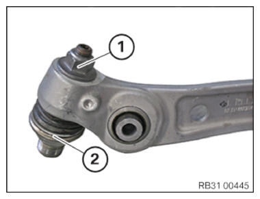
Installing the bottom wishbone
- Position the wheel guide joint (2) on the wishbone.
- Replace nut (1).
Parts: Nut
- Tighten nut (1).NOTE: Counter support on the Torx socket of the wheel guide joint (2).TIGHTENING TORQUES SPECIFICATION
Wheel control joint to wishbone M16
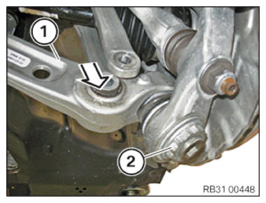
Replace nut.Joining torque 100 Nm Angle of rotation 90° - Position the wishbone (1) including wheel guide joint on the swivel bearing in direction of arrow.
- Replace nut (2).
Parts: Nut
- Tighten nut (2).TIGHTENING TORQUES SPECIFICATION
Wheel guide joint to swivel bearing M30
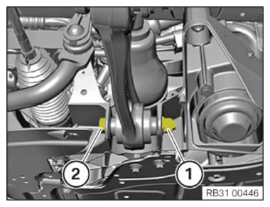
Replace nut.tightening torque 380 Nm NOTE: Tighten the screw connection in the NORMAL POSITION . - Position spring strut holder on wishbone.
- Replace screw (2) and the nut (1).
Parts: Bolt, nut
- Install the screw (2).
- Tighten the nut (1) in NORMAL POSITION
.TIGHTENING TORQUES SPECIFICATION
Bottom wishbone on spring strut holder M14
Replace screw and nut.
Tighten screw connection in normal position!Joining torque 165 Nm Angle of rotation 90° NOTE: Tighten the screw connection in the NORMAL POSITION . - Position the wishbone on the front axle support.
- Replace screw (2) and the nut (1).
Parts: Bolt, nut
- Insert screw and tighten the nut (2) in the NORMAL POSITION (1).
TIGHTENING TORQUES SPECIFICATION
| Lower wishbone to front axle carrier | ||
| M14 Replace screw and nut. Tighten in normal position. |
Joining torque | 85 Nm |
| Angle of rotation | 180° | |
Follow-up work
- Refer to INSTALLING THE COVER OF THE STEERING ASSEMBLY .
- Refer to ATTACHING THE FRONT LEFT WHEEL .
- Refer to PERFORMING CHASSIS ALIGNMENT CHECK .