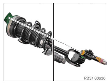
Align the spring strut and the spring strut support bearing with each other
CAUTION:
Laser beam.
Injury hazard!
Injury hazard!
- Do not look into the laser beam.
NOTE:
TECHNICAL INFORMATION
Laser class 2 according to standard EN60825-1 (1994) P ≤ 1 mW
Laser class 2 according to standard EN60825-1 (1994) P ≤ 1 mW
NOTE:
Schematic diagram is for example purposes. Some parts may differ in certain details.
- During the installation, it is absolutely necessary
to align the installation position of the spring strut with the installation position of the spring strut support bearing with the special tools 2 210 778
and 2 450 246.
This ensures a defined pre-tension at the screw connection of the spring strut fork at the bottom wishbone.
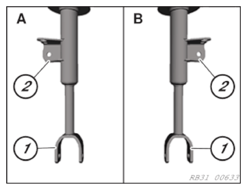
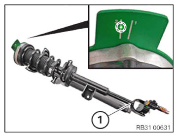
- Observe the alignment of the spring strut fork (1).
Left spring strut (Figure A): Stand for the anti-roll bar link (2) points from the top to the left.
Right spring strut (Figure B): Stand for the anti-roll bar link (2) points from the top to the right.
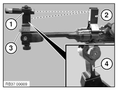
- Mount the laser (1) with the securing tool on the spring strut holder from the top.
- Place the mirror (2) vertical onto the spring strut!
- It is absolutely necessary
to set the mirror (2) onto a clean level surface!
Do not position the mirror (2) on labels or spot-welds!
The laser beam must face the mirror.
- Adjust the laser (1) with the adjustment screw (3) to project the laser beam via the mirror (2) to the mark (4).
- Remove the mirror (2).
The laser (1) can now no longer be adjusted (3) at the adjustment screw!
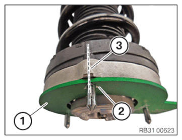
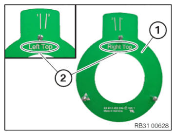
- Mount the 3 bolts to a special tool 2 450 246 (1).
- Align mark (2) on the special tool 2 450 246 (1) to mark (3) on the spring strut support bearing.
- Attach special tool 2 450 246
(1) on the spring strut support bearing.
- Left spring strut:
The (2) "Left Top" mark can now be read from the top on the special tool 2 450 246 (1)!
- Right spring strut:
The (2) "Right Top" mark can now be read from the top on the special tool 2 450 246 (1)!
- Align spring strut (1) with the mark on special tool 2 450 246
on the spring strut support bearing using a laser beam.
Mark on the shim:
- 1 = G32
- 2 = G30/G31/G38
Follow-up work
- Refer to RELIEVING TENSION ON COIL SPRING .
- Refer to INSTALLING THE FRONT SPRING STRUT .
- Refer to ATTACHING THE FRONT SPRING STRUT .
- Refer to SECURING THE SPRING STRUT TO THE BOTTOM WISHBONE .
- Refer to ATTACHING THE ANTI-ROLL BAR LINK TO THE SPRING STRUT .
- Refer to FASTENING THE TOP OF THE WISHBONE TO THE SWIVEL BEARING .
- Refer to REMOVING THE TOP SWIVEL BEARING ATTACHMENT .
- Refer to INSTALLING FRONT LEFT OR RIGHT WHEEL .
- Refer to INSTALLING THE COVER IN THE ENGINE COMPARTMENT AT THE REAR LEFT OR RIGHT .