Replacing all spark plugs
WARNING:
Hot surfaces.
Risk of burning!
Risk of burning!
- Perform all work only on components that have cooled down.
WARNING:
Hot fluids.
Risk of scalding!
Risk of scalding!
- Conduct all work in the vehicle wearing appropriate personal protective equipment only.
CAUTION:
Materials harmful to health.
Contact with fluids harmful to health!
Contact with fluids harmful to health!
- Note and follow safety instructions on containers.
- Conduct all work in appropriate personal protective equipment only.
NOTE:
TECHNICAL INFORMATION
Immobilization period-long fill of coolant!
Do not reuse used coolant.
When replacing and removing components which rely on the corrosion protection effect of the coolant, it is essential to change the coolant. The cooling system must therefore be emptied and refilled.
In the case of other removal work involving the draining of part quantities of coolant, the coolant level must be topped up with new coolant.
NOTE:
TECHNICAL INFORMATION
Notes on work at the cooling system form the basis of these repair instructions and must be complied with at all times.
For additional information see: INSTRUCTIONS FOR REPAIR WORK ON COOLING SYSTEM .
Notes on work at the cooling system form the basis of these repair instructions and must be complied with at all times.
For additional information see: INSTRUCTIONS FOR REPAIR WORK ON COOLING SYSTEM .
NOTE:
TECHNICAL INFORMATION
Collect and dispose of emerging fluids. Observe country-specific waste disposal regulations.
Collect and dispose of emerging fluids. Observe country-specific waste disposal regulations.
Preliminary work
- Refer to DISCONNECTING ALL BATTERY GROUND LEADS .
- Refer to REMOVING THE COVER OF THE RIGHT DME CONTROL UNIT .
- Refer to REMOVING THE CONTROL UNIT BRACKET FOR CYLINDERS 1 TO 4 .
- Refer to REMOVING THE COVER PANEL OF THE LEFT DME CONTROL UNIT .
- Refer to REMOVING TOP CLEAN AIR PIPE .
- Refer to REMOVING THE CONTROL UNIT BRACKET FOR CYLINDERS 5 TO 8 .
- Refer to PARTIAL REMOVAL OF COOLANT EXPANSION TANK .
- Refer to REMOVING ALL IGNITION COILS .
→ Removing the spark plug of cylinder bank 1
WARNING:
Hot surfaces.
Risk of burning!
Risk of burning!
- Perform all work only on components that have cooled down.
CAUTION:
Swirling dirt particles caused by compressed air.
Injury hazard!
Injury hazard!
- Collect dirt particles, e.g. when blowing out, use cloth to do so.
- Wear safety goggles.
NOTE:
TECHNICAL INFORMATION
Clean spark plug slot with compressed air.
The spark plug shaft must be cleaned using compressed air after having removed the ignition coils and before removing the spark plugs. After having removed the spark plugs, once again check the sealing surface for contamination and (if necessary) clean using a moist cloth or clean using compressed air.
Deposits that are not removed according to instructions may enter the combustion chamber and lead to uncontrolled combustion. Remaining deposits on the spark plug sealing surfaces may lead to leaks and the spark plugs may come loose during engine operation.
Spark plug threads must not be greased or oiled. Insufficiently tightened spark plugs may cause leaks and the sparks plugs may come loose during engine operation.
NOTE:
The description is for one component only. The procedure is identical for all further components.
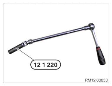
- Unscrew the spark plugs with the special tool 0 495 560 (12 1 220)
and an extension with joint.
Flexible ratchet extensions must always be used. If rigid mounting tools are used, there is a risk of insulator breakages.
Also, do not use a variable plug connection with locking capability as this poses a risk of insulator breakages.
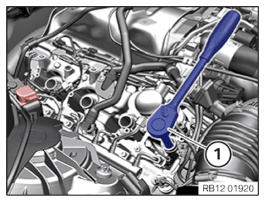
- Unscrew the spark plugs with the special tool 0 495 560 (12 1 220) and an extension with joint (1).
→ Removing spark plug of cylinder bank 2
WARNING:
Hot surfaces.
Risk of burning!
Risk of burning!
- Perform all work only on components that have cooled down.
CAUTION:
Swirling dirt particles caused by compressed air.
Injury hazard!
Injury hazard!
- Collect dirt particles, e.g. when blowing out, use cloth to do so.
- Wear safety goggles.
NOTE:
TECHNICAL INFORMATION
Clean spark plug slot with compressed air.
The spark plug shaft must be cleaned using compressed air after having removed the ignition coils and before removing the spark plugs. After having removed the spark plugs, once again check the sealing surface for contamination and (if necessary) clean using a moist cloth or clean using compressed air.
Deposits that are not removed according to instructions may enter the combustion chamber and lead to uncontrolled combustion. Remaining deposits on the spark plug sealing surfaces may lead to leaks and the spark plugs may come loose during engine operation.
Spark plug threads must not be greased or oiled. Insufficiently tightened spark plugs may cause leaks and the sparks plugs may come loose during engine operation.
Clean spark plug slot with compressed air.
The spark plug shaft must be cleaned using compressed air after having removed the ignition coils and before removing the spark plugs. After having removed the spark plugs, once again check the sealing surface for contamination and (if necessary) clean using a moist cloth or clean using compressed air.
Deposits that are not removed according to instructions may enter the combustion chamber and lead to uncontrolled combustion. Remaining deposits on the spark plug sealing surfaces may lead to leaks and the spark plugs may come loose during engine operation.
Spark plug threads must not be greased or oiled. Insufficiently tightened spark plugs may cause leaks and the sparks plugs may come loose during engine operation.
NOTE:
The description is for one component only. The procedure is identical for all further components.
- Unscrew the spark plugs with the special tool 0 495 560 (12 1 220) and an extension with joint.
Flexible ratchet extensions must always be used. If rigid mounting tools are used, there is a risk of insulator breakages.
Also, do not use a variable plug connection with locking capability as this poses a risk of insulator breakages.
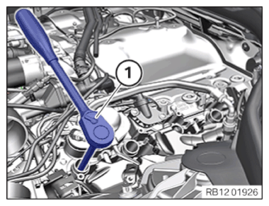
- Unscrew the spark plugs with the special tool 0 495 560 (12 1 220) and an extension with joint (1).
→ Installing spark plug of cylinder bank 2
NOTE:
The description is for one component only. The procedure is identical for all further components.
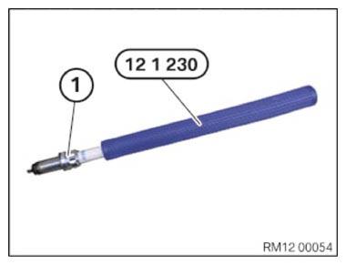
- Insert spark plug (1) into special tool 0 496 065 (12 1 230) .
NOTE:
TECHNICAL INFORMATION
Do not drop spark plug into spark plug shaft! This can lead to a reduction of the electrode gap and can thus impair smooth running of the engine, especially in idle position.
Do not drop spark plug into spark plug shaft! This can lead to a reduction of the electrode gap and can thus impair smooth running of the engine, especially in idle position.
- Make sure the spark plug does not fall into the spark plug shaft.
- First screw spark plugs into the engine using special tool 0 496 065 (12 1 230) and tighten manually.
NOTE:
TECHNICAL INFORMATION
Exclusively swiveling extensions may be used for the reversible ratchet. Rigid mounting tool and variable plug connections with rigid option may not be used; there is a risk that the insulator breaks.
Exclusively swiveling extensions may be used for the reversible ratchet. Rigid mounting tool and variable plug connections with rigid option may not be used; there is a risk that the insulator breaks.
- Tighten spark plugs with a torque wrench, special tool 0 496 065 (12 1 230) and extension with joint (1).
→ Installing the spark plug of cylinder bank 1
NOTE:
The description is for one component only. The procedure is identical for all further components.
- Insert spark plug (1) into special tool 0 496 065 (12 1 230) .
NOTE:
TECHNICAL INFORMATION
Do not drop spark plug into spark plug shaft! This can lead to a reduction of the electrode gap and can thus impair smooth running of the engine, especially in idle position.
Do not drop spark plug into spark plug shaft! This can lead to a reduction of the electrode gap and can thus impair smooth running of the engine, especially in idle position.
- Make sure the spark plug does not fall into the spark plug shaft.
- First screw spark plugs into the engine using special tool 0 496 065 (12 1 230) and tighten manually.
NOTE:
TECHNICAL INFORMATION
Exclusively swiveling extensions may be used for the reversible ratchet. Rigid mounting tool and variable plug connections with rigid option may not be used; there is a risk that the insulator breaks.
Exclusively swiveling extensions may be used for the reversible ratchet. Rigid mounting tool and variable plug connections with rigid option may not be used; there is a risk that the insulator breaks.
- Tighten spark plugs with a torque wrench, special tool 0 496 065 (12 1 230) and extension with joint (1).
Follow-up work
- Refer to REMOVING ALL IGNITION COILS .
- Refer to ATTACHING COOLANT EXPANSION TANK .
- Refer to INSTALLING THE CONTROL UNIT BRACKET FOR CYLINDERS 5 TO 8 .
- Refer to INSTALLING CLEAN AIR PIPE, TOP .
- Refer to INSTALLING THE COVER OF THE LEFT DME CONTROL UNIT .
- Refer to INSTALLING CONTROL UNIT HOLDER FOR CYLINDERS 1 TO 4 .
- Refer to INSTALLING THE COVER OF THE RIGHT DME CONTROL UNIT .
- Refer to CONNECTING NEGATIVE BATTERY CABLE .