Installing the ignition coil of cylinder bank 1
Prerequisite
Ignition is switched off.
NOTE:
RISK OF DAMAGE
Damage to the ignition coil.
The silicone hose of the ignition coil must not be contaminated by fuel as this can lead to failure of the ignition coil.
Damage to the ignition coil.
The silicone hose of the ignition coil must not be contaminated by fuel as this can lead to failure of the ignition coil.
- When working on the fuel system, cover the ignition coils with suitable materials and remove where required.
- Do not oil or grease the silicone tube of the spark plug socket. Do not use any protection or maintenance products (e.g. silicone spray, rubber care products, rust remover, etc.).
NOTE:
The description is for one component only. The procedure is identical for all further components.
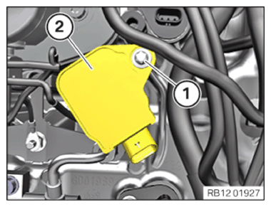
- Insert and install the ignition coil (2).
- Tighten down screw (1).
TIGHTENING TORQUES SPECIFICATION
| Ignition coil | ||
| screw | Tightening torque | 8 Nm |
- Feed in and install the cable clip (2).
- Tighten the screws (1).
TIGHTENING TORQUES SPECIFICATION
| Wiring harness on the cylinder head cover | ||
| M6x16 screw | Tightening torque | 10 Nm |
| Nut M6 | Tightening torque | 10 Nm |
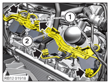
- Connect and lock connectors (arrows).
The connectors (arrows) must audibly engage.
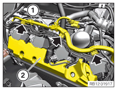
- Guide in and install cover (2).
- Insert and install cable (1).
- Secure the clamps (arrows).
→ Installing control unit holder for cylinders 1 to 4
NOTE:
RISK OF DAMAGE
Electrostatic discharge.
Damage to or destruction of electrical components.
Electrostatic discharge.
Damage to or destruction of electrical components.
- Leave the electrical components in their original packaging until they are being installed. Only use the original packaging for returning the product. Always package removed components straight away.
- Read and comply with user information on using the associated special tool 12 7 060.
- Only tap the housings of electrical components. Do not tap pins or multi-pin connectors directly.
- Wear electrically conductive clothing and antistatic shoes (with ESD symbol).
- For additional information see: NOTES ON ESD (ELECTROSTATIC DISCHARGE) PROTECTION .
NOTE:
TECHNICAL INFORMATION
Follow instructions for removing and installing control units.
For additional information see: 1200... INSTRUCTIONS FOR REMOVAL AND REPLACEMENT OF CONTROL UNITS .
Follow instructions for removing and installing control units.
For additional information see: 1200... INSTRUCTIONS FOR REMOVAL AND REPLACEMENT OF CONTROL UNITS .
NOTE:
TECHNICAL INFORMATION
Disconnecting control units may cause fault code entries and functional limitations. Fault code entries must be read out and deleted if necessary.
Disconnecting control units may cause fault code entries and functional limitations. Fault code entries must be read out and deleted if necessary.
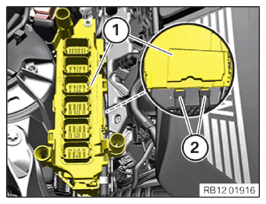
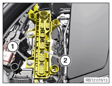
- Feed in the control unit bracket (1) with the DME control unit in the brackets (2) and install.
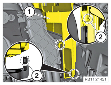
- Lock the control unit holder (1) on the retaining tabs (2).
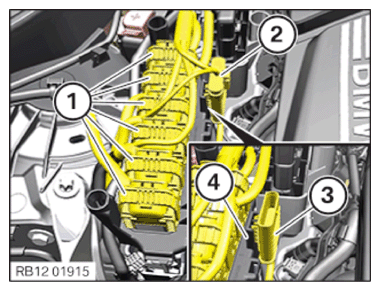
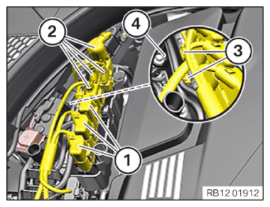
- Connect the connector (3) with bracket (4) and lock.
The connector (3) must engage audibly.
- Connect connectors (2) and lock.
The connector (2) must engage audibly.
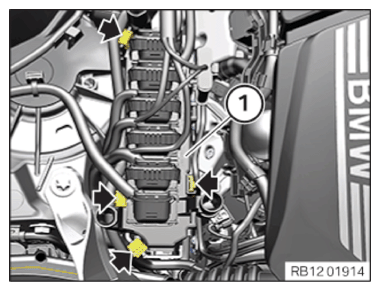
- Connect all connectors (1) and lock.
The connectors (1) must engage audibly.
- Fasten the clamps (arrows) to the control unit bracket (1).
- Feed in and install the control unit bracket (2) with control unit.
- Tighten the screws (1).
TIGHTENING TORQUES SPECIFICATION
| Control unit holder | ||
| Hexagon screw | Tightening torque | 8 Nm |
- Fasten the clamps (3) on the bracket (4).
- Connect connectors (2) and lock.
The connectors (2) must engage audibly.
- Connect connectors (1) and lock.
The connectors (1) must engage audibly.
→ Installing the cover of the right DME control unit
- Feed in the cover (1) in the guides and install it.