Installing the electrical machine electronics
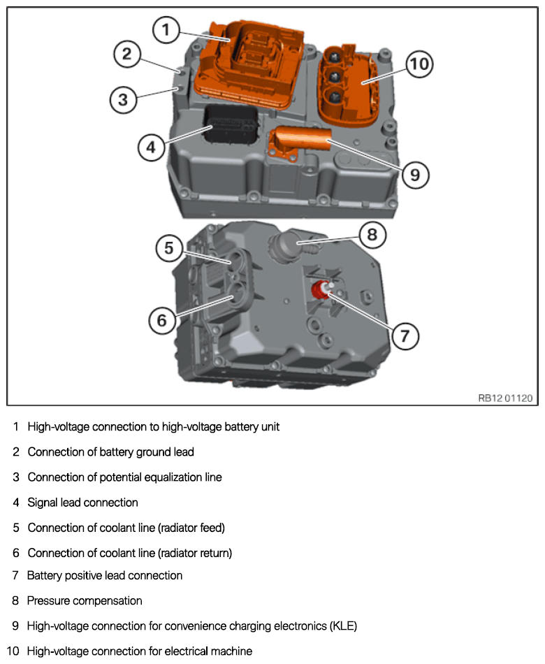
Connection overview for electrical machine electronics (EME)
CAUTION:
Heavy component.
Heavy components can lead to injury or damage.
Heavy components can lead to injury or damage.
- Remove and install heavy components with the aid of another person/other persons.
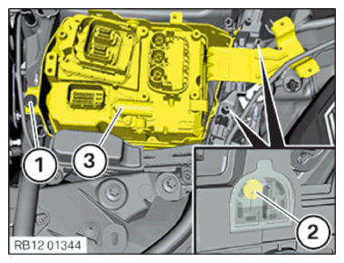
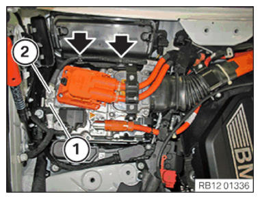
- Thread electrical machine electronics carefully in the units compartment and position.
- Tighten screws and clip the covers (2) into the units compartment.
TIGHTENING TORQUES SPECIFICATION
| Holder for electrical machine electronics to units compartment | ||
| Replace screws. M6x16 |
Tightening torque | 12 Nm |
| Angle of rotation | 90° | |
- Tighten down screw (1).
TIGHTENING TORQUES SPECIFICATION
| Holder for electrical machine electronics to body | ||
| Replace screws. M8x20 |
Tightening torque | 28 Nm |
| Angle of rotation | 90° | |
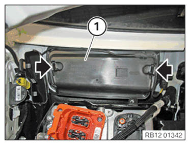
Install the cover for the fresh air inlet
- Install the cover for the fresh air inlet (1).
The cover for the fresh air inlet (1) must audibly snap into place.
- Replace O-ring.
Parts: O-ring.
- Connect coolant line (3) to the electrical machine electronics.
- Replace O-ring.
Parts: O-ring.
- Connect coolant line (2) to the electrical machine electronics.
- Tighten down screw (1).
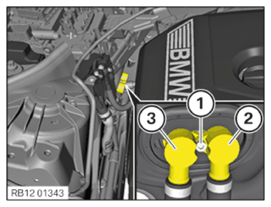
TIGHTENING TORQUES SPECIFICATION
| Coolant line to electrical machine electronics | ||
| M6x30 | Tightening torque | 8 Nm |
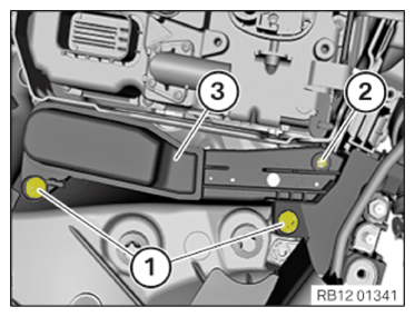
Installing the front power distribution box
- Position the power distribution box (3).
- Tighten the screws (1).
TIGHTENING TORQUES SPECIFICATION
| Front power distribution box | ||
| M8x35 screw | Tightening torque | 28 Nm |
- Tighten down screw (2).
TIGHTENING TORQUES SPECIFICATION
| Front power distribution box | ||
| Screw TS4x16 | Tightening torque | 2.6 Nm |
- Tighten nut (3) with the positive wire on the power distribution box (3).
TIGHTENING TORQUES SPECIFICATION
| Positive battery cable | ||
| Positive pole screw | tightening torque | 15 Nm |
- Tighten screw (2) with the positive battery cable on the power distribution box (3).
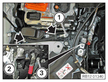
TIGHTENING TORQUES SPECIFICATION
| Auxiliary terminal for jump starting | ||
| Flange nut M8 | Tightening torque | 19 Nm |
- Clip in grounding cable on the power distribution box and tighten nuts (1).
TIGHTENING TORQUES SPECIFICATION
| Positive battery cable | ||
| Positive pole screw | tightening torque | 15 Nm |
» The rubber grommet of the grounding cable must be installed correctly.
- Install cover (1) and (2).
» Covers (1) and (2) must be correctly engaged.
NOTE:
TECHNICAL INFORMATION
Observe the additional information for unlocking and disconnecting various plug connections in electrical and hybrid vehicles!
Observe the additional information for unlocking and disconnecting various plug connections in electrical and hybrid vehicles!
TIGHTENING TORQUES SPECIFICATION
| High-voltage cable to electrical machine electronics | ||
| M6x25 Tighten screws in crosswise sequence. |
Joining torque | 3 Nm |
| Tightening torque | 8 Nm | |
- Position the upper section of the tension relief and tighten the screws (1).
TIGHTENING TORQUES SPECIFICATION
| Holder for tension relief | ||
| M6 | tightening torque | 8 Nm |
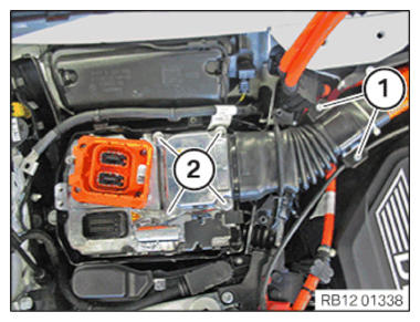
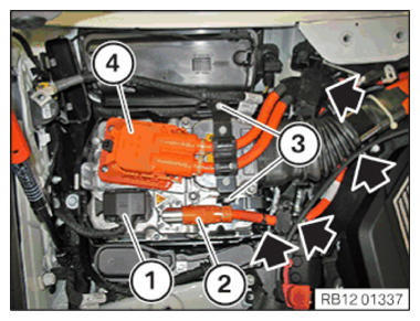
- Insert rubber grommet from the high-voltage cable (4) into the units compartment.
NOTE:
TECHNICAL INFORMATION
Observe the additional information for unlocking and disconnecting various plug connections in electrical and hybrid vehicles!
Observe the additional information for unlocking and disconnecting various plug connections in electrical and hybrid vehicles!
- Connect and lock the connector of the high-voltage cable (4).
- Tighten screws (3) from the tension relief.
TIGHTENING TORQUES SPECIFICATION
| Holder for tension relief | ||
| M6 | tightening torque | 8 Nm |
NOTE:
TECHNICAL INFORMATION
Observe the additional information for unlocking and disconnecting various plug connections in electrical and hybrid vehicles!
Observe the additional information for unlocking and disconnecting various plug connections in electrical and hybrid vehicles!
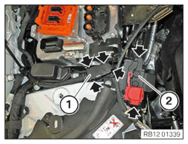
- Connect connector of the high-voltage cable (2) and lock.
- Clip in high-voltage cable (2) and insert the rubber grommet into the units compartment.
- Connect and lock the connector from signal line (1).
NOTE:
DANGER
Potential equalization in high-voltage system.
Mortal hazard if the potential equalization screw connection is not correct!
Potential equalization in high-voltage system.
Mortal hazard if the potential equalization screw connection is not correct!
- Observe the safety requirements for the potential equalization screw connection.
- Clean contact faces and have then checked by a second person.
- Tighten the screws/nuts for potential equalization with torque; have a second person check the torque.
- Correct execution of these tasks must be documented in the vehicle records by both persons.
- Tighten the screw (1) of the potential equalization line.
TIGHTENING TORQUES SPECIFICATION
| Potential equalization line to electrical machine electronics | ||
| M8x16 Observe notes on earth bonding screw connections! |
Tightening torque | 19 Nm |
NOTE:
DANGER
Potential equalization in high-voltage system.
Mortal hazard if the potential equalization screw connection is not correct!
Potential equalization in high-voltage system.
Mortal hazard if the potential equalization screw connection is not correct!
- Observe the safety requirements for the potential equalization screw connection.
- Clean contact faces and have then checked by a second person.
- Tighten the screws/nuts for potential equalization with torque; have a second person check the torque.
- Correct execution of these tasks must be documented in the vehicle records by both persons.
- Tighten the screw (2) of the battery ground lead.
TIGHTENING TORQUES SPECIFICATION
| Battery ground lead to electrical machine electronics | ||
| M8x16 Observe notes on earth bonding screw connections! |
Tightening torque | 19 Nm |
- Clip in the battery ground lead.
Follow-up work
- Refer to CONNECTING THE COOLANT LINES FOR THE LOW-TEMPERATURE COOLANT CIRCUIT (530e PHEV 2018-2020, 530e xDrive PHEV 2018-2020) , or CONNECTING THE COOLANT LINE OF LOW-TEMPERATURE COOLANT CIRCUIT (530e PHEV 2021-2022, 530e xDrive PHEV 2021-2022) .
- Refer to FILLING THE LOW-TEMPERATURE COOLING SYSTEM WITH THE VACUUM FILLING EQUIPMENT .
- Refer to INSTALLING RIGHT SEALING FRAME .
- Refer to INSTALLING THE CENTER COWL UPPER PART .
- Refer to INSTALLING TENSION STRUT ON SHOCK TOWER .
- Refer to INSTALLING WINDSHIELD PANEL COVER .
- Refer to INSTALLING LEFT AND RIGHT WIPER ARM .
- Refer to INSTALLING THE REAR RIGHT ENGINE COMPARTMENT COVER .
- Refer to INSTALLING THE COVER OF THE ENGINE COMPARTMENT ON THE REAR LEFT .
- Refer to TAKING HOOD OUT OF THE SERVICE POSITION .
- Refer to CONNECTING NEGATIVE BATTERY CABLE .
- Refer to ACTIVATING HIGH-VOLTAGE SYSTEM .
- Refer to INSTALLING FLAP IN RIGHT LUGGAGE COMPARTMENT TRIM PANEL .
- Refer to INSTALLING THE FRONT UNDERBODY PROTECTION OR FRONT THRUST FIELD .
- Refer to VENTING THE LOW-TEMPERATURE COOLING SYSTEM (530e PHEV 2018-2020, 530e xDrive PHEV 2018-2020) , or VENTING THE LOW-TEMPERATURE COOLING SYSTEM (530e PHEV 2021-2022, 530e xDrive PHEV 2021-2022) .
- Refer to ENCODE/PROGRAM CONTROL UNIT(S) .
- Refer to PERFORMING ROTOR POSITION SENOR CALIBRATION .