Remove the engine wiring harness for sensor system 1
NOTE:
DANGER
High-voltage system.
The high-voltage system operates on the basis of hazardous, electrical voltage and high currents. Mortal hazard through electric shock!
High-voltage system.
The high-voltage system operates on the basis of hazardous, electrical voltage and high currents. Mortal hazard through electric shock!
- All work on the high-voltage system may only be carried out by specially trained and technically experienced personnel.
- For additional information see:
- For additional information see:
WARNING:
Working on 12 V electrical system.
Risk of short circuits! Risk of fire!
Risk of short circuits! Risk of fire!
- Make sure that there is no charger connected to the jump start terminal in the engine compartment.
- Detach battery ground lead from battery.
- For auxiliary batteries: Detach battery minus cables from all auxiliary batteries.
NOTE:
RISK OF DAMAGE
Damage to battery terminal, the safety battery terminal or the intelligent battery sensor (IBS).
Damaged battery terminals can lead to malfunctions or vehicle electrical system faults.
Damage to battery terminal, the safety battery terminal or the intelligent battery sensor (IBS).
Damaged battery terminals can lead to malfunctions or vehicle electrical system faults.
- Detach battery terminal from battery pole by carefully shifting to and fro. Do not pry off using a tool.
NOTE:
TECHNICAL INFORMATION
Additional coolant can leakage. Make sure that no coolant enters the intake port of the cylinder head.
Additional coolant can leakage. Make sure that no coolant enters the intake port of the cylinder head.
NOTE:
TECHNICAL INFORMATION
Collect and dispose of emerging fluids. Observe country-specific waste disposal regulations.
Collect and dispose of emerging fluids. Observe country-specific waste disposal regulations.
Preliminary work
- Refer to BRINGING FRONT COMPARTMENT LID IN THE SERVICE POSITION .
- Refer to DISCONNECTING ALL BATTERY GROUND LEADS .
- Refer to REMOVING THE SEAL FOR THE HOOD REAR .
- Refer to REMOVING THE ACOUSTIC COVER .
- Refer to REMOVING ACOUSTIC COVER AT REAR .
- Refer to REMOVING THE DME CONTROL UNIT .
- Refer to REMOVING THE INTEGRATED POWER SUPPLY MODULE (PDM) .
- Refer to REMOVING CONTROL UNIT BRACKET .
- Refer to REMOVING RESONATOR .
- Refer to REMOVING THE FRONT UNDERBODY PROTECTION OR FRONT THRUST FIELD .
- Refer to REMOVING THE UNDERBODY PROTECTION OF THE STEERING GEAR AND THRUST FIELD RESPECTIVELY .
- Refer to REMOVING REAR THRUST FIELD .
- Refer to REMOVING REAR UNDERBODY PROTECTION .
- Refer to REMOVING THE THERMOSTAT FROM THE TRANSMISSION OIL LINES .
- Refer to DRAINING THE COOLANT FROM THE LOW-TEMPERATURE COOLING SYSTEM .
- Refer to CONNECTING THE COOLANT LINE OF LOW-TEMPERATURE COOLANT CIRCUIT .
- Refer to REMOVING TANK VENT VALVE .
- Refer to REMOVING THE INTAKE PLENUM .
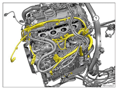
Engine wiring harness for sensor system 1
NOTE:
RISK OF DAMAGE
Damage to wires when disconnecting connectors and plug connections.
Sheared wires can cause a short circuit.
Damage to wires when disconnecting connectors and plug connections.
Sheared wires can cause a short circuit.
- Do not pull on wires when disconnecting connectors and plug connections.
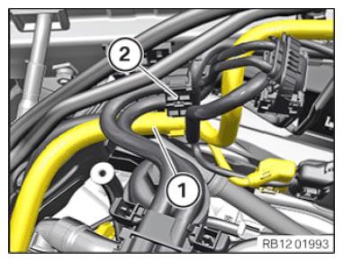
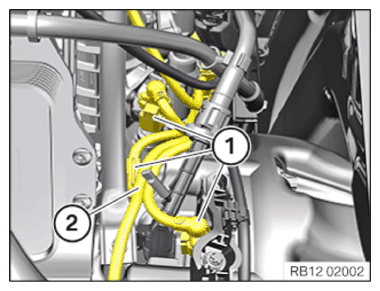
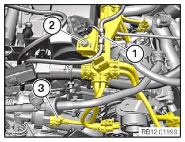
- Guide out the wiring harness section (1) for the sensor system 1 from the holder (2) and place to one side.
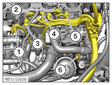
- If fitted:
Unlock and disconnect plug connections (1).
- Unlock and disconnect plug connections (2) from the knock sensors.
- Unlock and disconnect connector (3) from the changeover valve.
- Unlock and disconnect connector (4) from the component temperature sensor.
- Unlock and disconnect connector (5) from the temperature sensor.
- Unlock and disconnect the connector (6) from the heat management module.
- Guide out the wiring harness section for sensor system 1 and set it aside.
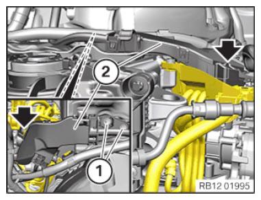
- Loosen screws (1).
- Unlock the lock (arrow).
- Remove the wiring harness section (2) and put to one side.
- Loosen screws (1).
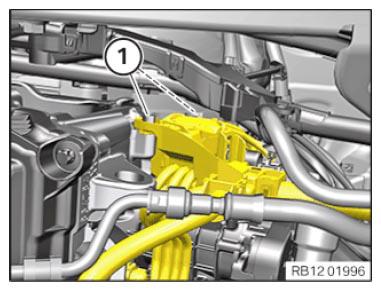
- Unlock and disconnect plug connections (1).
- Guide out the wiring harness section (2) for sensor system 1 and place to one side.
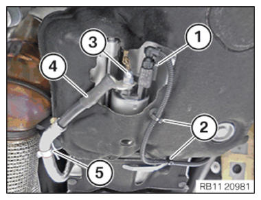
- Unlock plug connection (1) and disconnect.
- Loosen clamps (2).
- Loosen nut (3).
- Guide the positive battery cable (4) out of the clamp (5) and lay to one side.
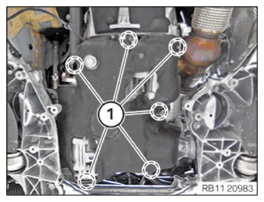
- Release all expanding rivets (1) in the marked area.
- Feed out the oil sump acoustic cover and remove.
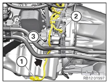
- Unlock plug connection (1) and disconnect.
- Unlock and disconnect plug connections (2).
- Release the wiring harness section (3) for sensor system 1 from the clamp (arrow) and place to one side.
- Remove the wiring harness section (1) and put to one side.
- Loosen screw (2).
- Unlock plug connection (3) and disconnect.
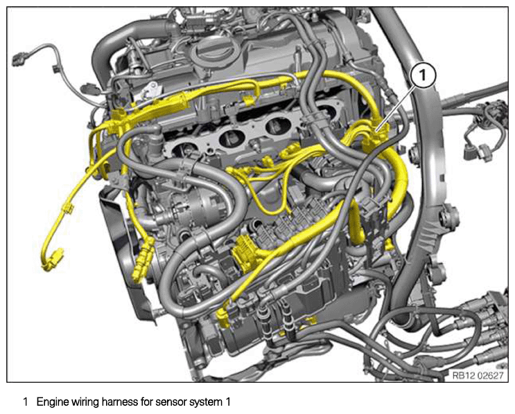
- Feed out the wiring harness section (1) for sensor system 1 and remove.