Removing the wiring harness section for the injectors of cylinders 1 to 4
NOTE:
RISK OF DAMAGE
Electrostatic discharge.
Damage to or destruction of electrical components.
Electrostatic discharge.
Damage to or destruction of electrical components.
- Leave the electrical components in their original packaging until they are being installed. Only use the original packaging for returning the product. Always package removed components straight away.
- Read and comply with user information on using the associated special tool 12 7 060.
- Only tap the housings of electrical components. Do not tap pins or multi-pin connectors directly.
- Wear electrically conductive clothing and antistatic shoes (with ESD symbol).
- For additional information see: NOTES ON ESD (ELECTROSTATIC DISCHARGE) PROTECTION .
NOTE:
RISK OF DAMAGE
Malfunction or failure of the DME.
Grounding points that are not screwed on may lead to malfunction or failure of the DME.
Malfunction or failure of the DME.
Grounding points that are not screwed on may lead to malfunction or failure of the DME.
- Screw all screw points of the cable ducts on again. Some of the screw points are also grounding points.
NOTE:
TECHNICAL INFORMATION
Disconnecting control units may cause fault code entries and functional limitations. Fault code entries must be read out and deleted if necessary.
Disconnecting control units may cause fault code entries and functional limitations. Fault code entries must be read out and deleted if necessary.
Preliminary work
- Refer to DISCONNECTING ALL BATTERY GROUND LEADS .
- Refer to REMOVING THE COVER ON LEFT AND RIGHT IN THE ENGINE COMPARTMENT AT THE TOP .
- Refer to REMOVING REAR UNDERBODY PROTECTION .
- Refer to REMOVING THE ACOUSTIC COVER .
- Refer to REMOVING INTAKE SILENCER HOUSING .
- Refer to REMOVING THE LEFT AND RIGHT FRONT-END STRUT .
- Refer to REMOVING FRONT CROSS CONNECTION .
- Refer to REMOVING THE REAR TOP CROSS CONNECTION .
- Refer to REMOVING THE RIGHT UNFILTERED-AIR DUCT .
- Refer to PARTIALLY RELEASING THE RIGHT CHARGE AIR LINE .
- Refer to REMOVING RIGHT CLEAN AIR PIPE .
- Refer to REMOVING COVER FOR THE RIGHT DME CONTROL UNIT .
- Refer to REMOVING THE DME CONTROL UNIT FOR CYLINDERS 1 TO 4 .
- Refer to REMOVE THE INTEGRATED POWER SUPPLY MODULE (PDM) .
- Refer to REMOVING THE HOLDER FOR THE RIGHT-HAND DME CONTROL UNIT .
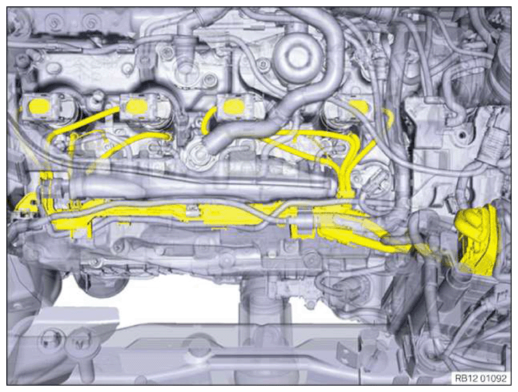
Wiring harness for the injectors of cylinders 1 to 4
NOTE:
RISK OF DAMAGE
Malfunction or failure of the DME.
Grounding points that are not screwed on may lead to malfunction or failure of the DME.
Malfunction or failure of the DME.
Grounding points that are not screwed on may lead to malfunction or failure of the DME.
- Screw all screw points of the cable ducts on again. Some of the screw points are also grounding points.
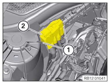
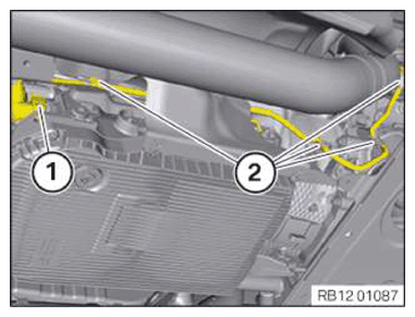
- Unlock the locks (1).
- Remove the cover (2) in an upwards direction.
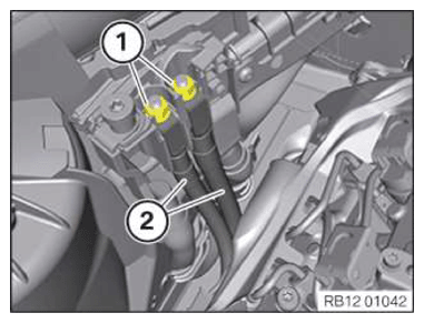
- Loosen nuts (1).
- Remove positive battery cables (2).
- Loosen screws (1).
- Unlock connector (1) and remove from transmission.
- Release and expose the cable from the clamps (2).
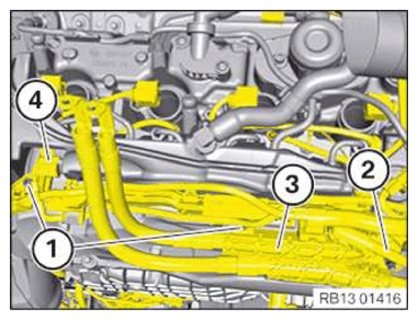
- Loosen screws (1).
- Loosen nut (2).
- Remove ground cable.
- Loosen ground pin underneath and unscrew.
- Place positive battery cables, together with cable clip (3), to one side.
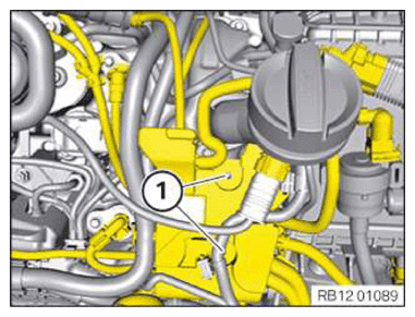
- Unlock connector (4) and detach from the rail pressure sensor.
NOTE:
The description is for one component only. The procedure is identical for all further components.
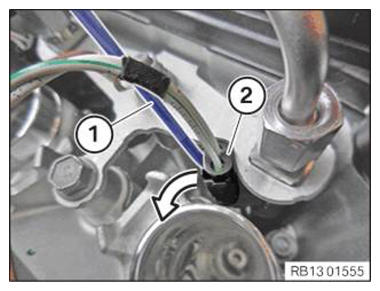
- Unlock connector fastener (1) of ignition coil and detach connector (2) from ignition coils of cylinders 1 to 4.
NOTE:
Schematic diagram is for example purposes. Some parts may differ in certain details.
- Unlock and disconnect the connectors (2) from the injectors with a small slotted screwdriver (1).
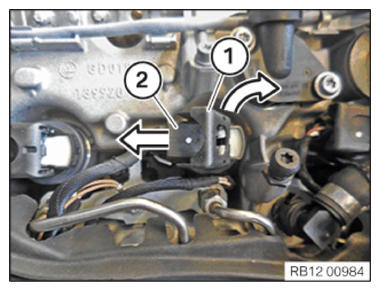
- Unlock the lock in the direction of the arrow with a small slotted screwdriver (1).
- Disconnect the connector (2) on the connector housing from the injector.
- Unlock and detach connector (1) from injectors.
- Loosen nuts (2).
- Remove ground cable.
- Disconnect the wiring harness section for the injectors of cylinders 1 to 4 (3) from the other wiring harnesses.
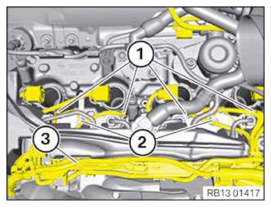
- Guide out the wiring harness section for the injectors of cylinders 1 to 4 and remove.