Remove the vehicle wiring harness of the integrated power supply module (PDM)
Prerequisite
- Ignition is switched off.
NOTE:
RISK OF DAMAGE
Electrostatic discharge.
Damage to or destruction of electrical components.
Electrostatic discharge.
Damage to or destruction of electrical components.
- Leave the electrical components in their original packaging until they are being installed. Only use the original packaging for returning the product. Always package removed components straight away.
- Read and comply with user information on using the associated special tool 12 7 060.
- Only tap the housings of electrical components. Do not tap pins or multi-pin connectors directly.
- Wear electrically conductive clothing and antistatic shoes (with ESD symbol).
- For additional information see: NOTES ON ESD (ELECTROSTATIC DISCHARGE) PROTECTION .
NOTE:
RISK OF DAMAGE
Malfunction or failure of the DME.
Grounding points that are not screwed on may lead to malfunction or failure of the DME.
Malfunction or failure of the DME.
Grounding points that are not screwed on may lead to malfunction or failure of the DME.
- Screw all screw points of the cable ducts on again. Some of the screw points are also grounding points.
NOTE:
TECHNICAL INFORMATION
Disconnecting control units may cause fault code entries and functional limitations. Fault code entries must be read out and deleted if necessary.
Disconnecting control units may cause fault code entries and functional limitations. Fault code entries must be read out and deleted if necessary.
Preliminary work
- Refer to REMOVING THE COVER ON LEFT AND RIGHT IN THE ENGINE COMPARTMENT AT THE TOP .
- Refer to REMOVING THE ACOUSTIC COVER .
- Refer to REMOVING INTAKE SILENCER HOUSING .
- Refer to REMOVING THE LEFT AND RIGHT FRONT-END STRUT .
- Refer to REMOVING FRONT CROSS CONNECTION .
- Refer to REMOVING THE REAR TOP CROSS CONNECTION .
- Refer to REMOVING FAN COWL .
- Refer to REMOVING THE LEFT UNFILTERED-AIR DUCT .
- Refer to REMOVING THE RIGHT UNFILTERED-AIR DUCT .
- Refer to REMOVING COVER FOR THE RIGHT DME CONTROL UNIT .
- Refer to REMOVING COVER FOR THE DME CONTROL UNIT ON LEFT .
Wiring harness of the integrated power supply module (PDM)
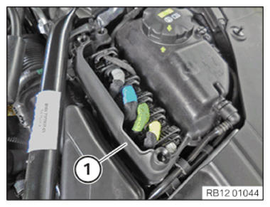
- Unlock and remove the cover (1).
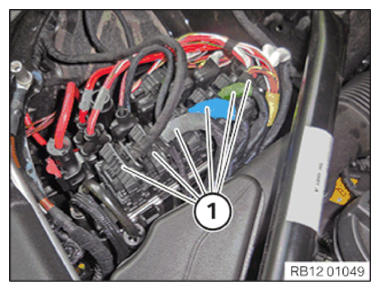
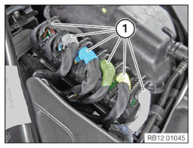
- Unlock all connectors (1) from the rear to the front and then detach them off of the DME control unit.
- Detach all cables (1) from the DME control unit holder.
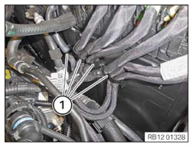
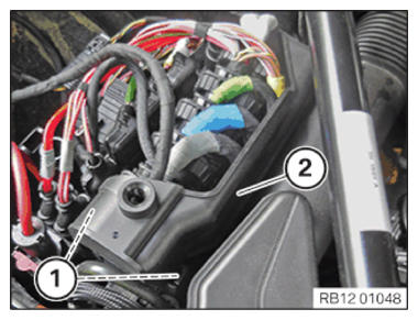
- Unlock the locks (1).
- Remove cover (2).
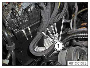
- Unlock all connectors (1) and detach from the DME control unit.
- Detach all cables (1) from the DME control unit holder.
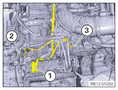
- Unlock the connectors (1) and pull off from the DME control unit for cylinders 5 to 8.
- Unlock and disconnect the connector (2) from the auxiliary coolant pump.
- Loosen screw (3).
- Remove ground cable.
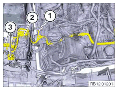
- Loosen the nut (1) and remove the ground cable.
- Unlock the connectors (2) and pull off from the DME control unit for cylinders 1 to 4.
- Unlock connector (3) and remove.
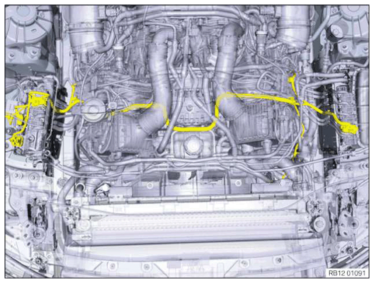
- Loosen, feed out and remove the wiring harness from the clamps.