Installing the control unit bracket for cylinders 5 to 8
NOTE:
RISK OF DAMAGE
Electrostatic discharge.
Damage to or destruction of electrical components.
Electrostatic discharge.
Damage to or destruction of electrical components.
- Leave the electrical components in their original packaging until they are being installed. Only use the original packaging for returning the product. Always package removed components straight away.
- Read and comply with user information on using the associated special tool 12 7 060.
- Only tap the housings of electrical components. Do not tap pins or multi-pin connectors directly.
- Wear electrically conductive clothing and antistatic shoes (with ESD symbol).
- For additional information see: NOTES ON ESD (ELECTROSTATIC DISCHARGE) PROTECTION .
NOTE:
RISK OF DAMAGE
Follow instructions for removing and installing control units.
For additional information see: INSTRUCTIONS FOR REMOVAL AND REPLACEMENT OF CONTROL UNITS .
Follow instructions for removing and installing control units.
For additional information see: INSTRUCTIONS FOR REMOVAL AND REPLACEMENT OF CONTROL UNITS .
NOTE:
TECHNICAL INFORMATION
Disconnecting control units may cause fault code entries and functional limitations. Fault code entries must be read out and deleted if necessary.
Disconnecting control units may cause fault code entries and functional limitations. Fault code entries must be read out and deleted if necessary.
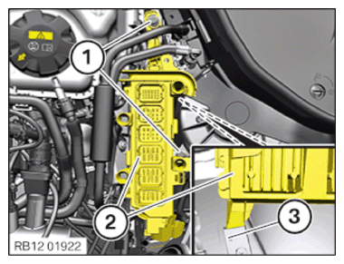
- Guide and install control unit bracket (2) with the DME control unit into holder (3).
- Tighten down screws (1).
TIGHTENING TORQUES SPECIFICATION
| Control unit holder | ||
| Hexagon screw | Tightening torque | 8 Nm |
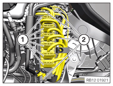
- Fasten all the clamps (2).
- Connect all connectors (1) and lock.
The connectors (1) must engage audibly.
Follow-up work
- Refer to INSTALLING CLEAN AIR PIPE, TOP .
- Refer to INSTALLING THE COVER OF THE LEFT DME CONTROL UNIT .
- Refer to CONNECTING NEGATIVE BATTERY CABLE .